


46
GB MT
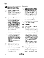
Dismantling the spacer:
5. To remove the spacer, loosen
the 3 cross-head screws on the
protective cover (8) and remove
the protective cover and spacer
(10).
6. Remount the protection cover
(8).
Mounting the additional handle:
1. Unscrew the screw (11) on the
additional handle included in de-
livery (12).
2. Pull the ends of the additional
handle (12) apart and push this
over the handle holder (16).
3. Screw on the additional handle
(12) using the screw (11).
Operation
WARNING: Danger of injury!
Never use the trimmer without its
protective cover. Always check
the operability of the trimmer
before it is used. Check that the
mains voltage is the same as
indicated on the rating plate. Al-
ways wear goggles when work-
ing with the trimmer.
Please observe local regulations
concerning noise protection.
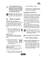
Switching ON and OFF
1. Remove the protection card-
board packaging on the line cut-
ter (
13).
2. Form a loop in the end of the ex-
tension cable, conduct it through
the opening in the upper handle
(1) and hang it on to the strain
relief (4).
3. Connect the trimmer to the
mains socket.
4. Ensure a safe stance and hold
the equipment firmly with both
hands. Do not deposit the cutting
head on the ground.
5. To switch on depress the ON
/ OFF switch (2). Release the
switch to switch off.
After the trimmer has been
switched off the cutting head will
continue to rotate for a few sec-
onds. Keep hands and feet well
away. There is the danger of cut-
ting damage.
Risk of injury from cuts.
The ON / OFF switch must not
be locked in place. The trimmer
must not be used if the switch is
damaged. There is the immedi-
ate danger of injury if the motor
does not switch off after the ON /
OFF switch has been released.
Caution:
Always remove grass
residue from the line cutter so that
the cutting effect is not impaired.
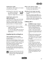
Trimmer settings
Adjusting the additional handle:
The additional handle can be set in dif-
ferent positions. Set the handle in such a
manner that the cutting head is slightly tilt-
ing forwards when in the working position.
Release the knurled nut (11) and
adjust the additional handle (12) in
the required position. Retighten
the knurled nut.
Содержание FRT 450 A1
Страница 3: ...1 2 3 4 5 6 7 8 9 9 14 15 10 10 7 8 11 10 7 12 13 8 8 ...
Страница 4: ...1 2 4 5 11 10 17 19 15 17 14 13 18 11 12 12 16 6 9 9 ...
Страница 52: ...52 GB MT ...
Страница 68: ...68 ...