


Flomatic Corp, 15 Pruyn’s Island, Glens Falls, New York 12801
Phone: 518-761-9797 Fax: 518-761-9798 www.flomatic.com
745PI-BF-LS-ASC Rev. B
October 12, 2018
INSTALLATION
Correct installation of the Flomatic
®
Flo-Flex
®
is important for proper
operation. It may be installed in either horizontal or vertical flow-up
applications. Horizontal installation, with the access port facing up is
recommended for waste water application as it will prevent material
in the fluid to collect on the valve disc. In all installations, the flow
arrow cast in the valve and cover must be pointed in the direction of
flow.
Flanged valves should only be mated with flat-faced pipe flanges
equipped with full-face resilient gaskets. The valve and adjacent
piping must be supported and aligned to prevent cantilevered stress
on the valve. Once the flange bolts or studs are lubricated and
inserted around the flange, tighten them uniformly hand tight. The
tightening of the bolts should then be done in graduated steps using
the
crossover tightening
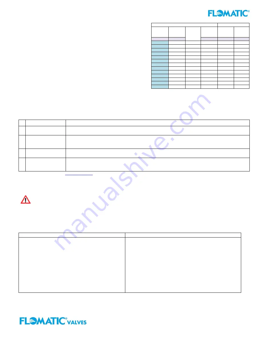
method. Recommended lubricated torque
values for use with resilient gaskets (75 durometer) are given in Table 1. If leakage occurs, allow gaskets to absorb fluid
and check torque and leakage after 24 hours. Do not exceed bolt rating or the flange gasket can get damaged and extrude.
TROUBLESHOOTING
Below are some potential problems with solutions to assist you in troubleshooting the valve assembly in a safe manner.
Also, visit Flomatic
®
web page
www.flomatic.com
for technical product references and parts lists or call customer service 1-800-833-2040.
MAINTENANCE
The Flomatic
®
Flo-Flex
®
Swing Check Valve requires no scheduled lubrication or maintenance. For service or inspection,
the valves internal parts can be accessed and serviced without removal from the line.
WARNING: The line must be drained and de-pressurized before removing the cover or the bottom plug if
not this may cause bodily harm.
VALVE INSPECTION: DISASSEMBLY & RE-ASSEMBLY
The valves internal parts can be disassembled and serviced without removing it from the pipeline. All service and repair
work performed on the valve shall be performed by a skilled mechanic with proper tools and a power hoist for larger
valves. It is recommended that when disassemble the valve to inspect the rubber valve disc for wear or the valve seat for
deposits.
Dimensions for 150# Class Valves
Max Torque
Valve
Size
Flange
Outside
Diameter
Number
of Bolt
Holes
Bolt
Diameter
150# 300#
(inches)
(inches)
(inches)
(ft.-lbs.)
(ft.-lbs.)
2 6 4
5/8”
90
90
2-1/2 7 4 5/8” 90 150
3 7-1/2 4 5/8” 90 150
4 9 8
5/8”
90
150
6 11 8
3/4”
150
150
8 13-1/2 8 3/4” 150 240
10 16 12
7/8”
240
368
12 19 12
7/8”
240
533
14 21 12 1” 368
533
16 23-1/2 16 1” 368 750
18 25 16
1-1/8”
533
750
20 27-1/2 20 1-1/8” 533 750
24 32 20
1-1/4”
750
1200
Table 1
Bolt Torque Chart
Problem Solution
1
Valve disc leaks-
back when closed
Inspect valve seat area for foreign material. Also, inspect disc for damage and replace. Inspect metal
seating surface and clean if necessary
2
Leakage at bottom
Back-flush device
Remove line pressure and exercise Back-flush device. If leak persists, replace seals in Back-flush
device; see the Back-flush device “Seal Replacement Procedure” on page 4.
3
Leakage at Cover or
Flanges
Tighten bolts, replace cover seal.
4
Valve does not fully
open:
Check for obstruction in valve seat area and/or pipeline; see Disassembly procedure on page 4.
Operating pressure may be less than cracking pressure. If less than 0.5 psig, review application with
factory.
DISASSEMBLY
RE-ASSEMBLY
1. Relieve pressure and drain the pipeline. Refer to
Figure 2 on page 2. Remove the cover bolts (5)
on the top cover.
2. Pry cover (2) loose and lift off valve body. 12” and
larger valves have tapped holes in cover for lifting
eyes.
3. Remove disc (3) and inspect for cracks, tears or
damage in rubber sealing surface.
4.
Clean and inspect parts. Replace worn parts as
necessary and lubricate parts with FDA/NSF
grease such as “Super Lube”.
All parts must be cleaned. Gasket surfaces should be cleaned
with a stiff wire brush in the direction of the serrations or machine
marks. Worn parts, gaskets and seals should be replaced during
reassembly.
1. Lay disc (3) over seat with beaded seating surface
directed down.
2. Lay cover gasket (4) and cover (2) over bolt holes and
disc hinge.
3. Insert lubricated bolts (5) noting that the bolts in the
hinge area are longer than the other cover bolts.
4.
Cover bolts should be tightened to the specifications
shown in
Table 2
(next page) during re-assembly.


