background image

13                                  MG302-EU-EN V2.0   4/11 


PC WIRELESS COMMUNICATION 

1. 

Install and launch the PC software (refer to the HELP utility contained in the software for more 
details) 

2. 

Press and Hold the backlight/USB button for two seconds to enter RF wireless transmit mode 

3. 

The RF icon 

 will appear on the display 

4. 

When communication is established, the RF icon on the display will blink and the LED indicator 
on the receiver will blink 

5. 

Once per second, the data will be displayed on the PC screen (plotted on the graph and 
inserted to the data list) 

6. 

Hold the backlight button for two seconds to exit the RF wireless transmit mode 

SENDING STORED DATA TO THE PC 

1. 

Launch the PC software  

2. 

Press the STORE button for two seconds to enter into data RECALL function. 

3. 

Press the HOLD button for two seconds. The RF transmit icon will flash while the stored data is 
sent to the PC 


NOTE: Refer to the HELP utility included in the supplied software program for in-depth 
software instructions. 

SETUP 

1. 

Press and Hold the RANGE/SETUP button for two seconds to enter the SET function. The first 
of five settable functions will appear. 

2. 

Press the RANGE button to step through the functions 
a: Alarm High limit buzzer alarm 

OFF or Value 

b: Alarm Low limit buzzer alarm 

OFF or Value 

c: Auto power off time 

OFF, 10 to 30 sec 

d: Button beeper 

ON/OFF 

e : Back light time 

OFF, 10 to 30 sec 

3. 

Use the +, - ,

 and 

 buttons to select and change conditions and digits. 

4. 

Press the RANGE/SETUP button until the meter returns to the normal display to exit this mode. 

ALARM LIMITS 

1. 

Press and Hold the SETUP button for two seconds to enter the High Limit function. 

2. 

Press the 

 button to select a digit for adjustment 

3. 

Press the + or – button to adjust the value of the digit 

4. 

Press the 

 button to turn the alarm OFF. 

5. 

Press the SETUP button and repeat the procedure to set the low limit 

6. 

Press the SETUP button to step through the other functions and return to the normal operating 
mode. 

7. 

The meter will “beep” if the measured value is greater than the high limit or lower than the low 
limit. 

LOW BATTERY INDICATION 

When the 

 icon appears in the display, the battery should be replaced. 


Содержание Extech Instruments MG302

Страница 1: ...User s Guide Wireless TRMS Multimeter and Insulation Tester Model MG302...

Страница 2: ...nd exceeds in this case 1000 VAC or VDC This symbol adjacent to one or more terminals identifies them as being associated with ranges that may in normal use be subjected to particularly hazardous volt...

Страница 3: ...IEC 61010 2 USE EXTREME CAUTION when working with high voltages 3 DO NOT measure voltage if the voltage on the COM input jack exceeds 1000V above earth ground 4 NEVER connect the meter leads across a...

Страница 4: ...unciators Continuity Diode test Battery status n nano 10 9 capacitance micro 10 6 amps cap m milli 10 3 volts amps A Amps k kilo 103 ohms F Farads capacitance M mega 106 ohms RF transmitter active Ohm...

Страница 5: ...be long enough to contact the live parts inside some 240V outlets for appliances because the contacts are recessed deep in the outlets As a result the reading may show 0 volts when the outlet actually...

Страница 6: ...lack test lead banana plug into the negative COM jack 2 For current measurements up to 4000 A DC set the function switch to the A position and insert the red test lead banana plug into the A mA jack 3...

Страница 7: ...Touch the black test probe tip to the neutral side of the circuit Touch the red test probe tip to the hot side of the circuit 9 Apply power to the circuit 10 Read the current in the display 11 In the...

Страница 8: ...M jack and the red test lead banana plug into the positive V jack 3 Press the MODE button to indicate and V on the display 4 Touch the test probes to the diode under test Forward voltage will typicall...

Страница 9: ...es 5 Read the temperature in the display Note The temperature probe is fitted with a type K mini connector A mini connector to banana connector adaptor is supplied for connection to the input banana j...

Страница 10: ...ss the TEST button to start a hands free test Note If the circuit under test is live and has a voltage potential AC DC over 30V the meter it will not test the display will show 30V the symbol will fla...

Страница 11: ...appear The right most auxiliary display will show and hold the minimum reading updating only when a new MIN occurs 2 To exit MAX MIN mode press EXIT RELATIVE MODE The relative measurement mode displa...

Страница 12: ...the desired sample rate 0 to 255 seconds 4 Set the sample rate to 0000 S for manual recording In this mode each press of the STORE button will save one measurement reading 5 Set the sample rate from...

Страница 13: ...tions SETUP 1 Press and Hold the RANGE SETUP button for two seconds to enter the SET function The first of five settable functions will appear 2 Press the RANGE button to step through the functions a...

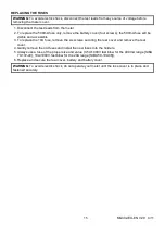
Страница 14: ...e old or weak batteries so they do not leak and damage the unit 6 IF THE METER IS TO BE STORED FOR A LONG PERIOD OF TIME the batteries should be removed to prevent damage to the unit BATTERY INSTALLAT...

Страница 15: ...cessible 3 To replace the 10A fuse remove the six screws securing the rear cover and remove the rear cover 4 Gently remove the old fuses and install the new fuses into the holders 5 Always use a fuse...

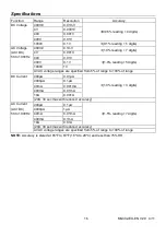
Страница 16: ...1000V 1V All AC voltage ranges are specified from 5 of range to 100 of range DC Current 400 A 0 01 A 1 0 reading 3 digits 4000 A 0 1 A 40mA 0 001mA 400mA 0 01mA 10A 0 001A 20A 30 sec max with reduced...

Страница 17: ...z 0 0001MHz 40MHz 0 001MHz 100MHz 0 01MHz Not specified Sensitivity 0 8V rms min 20 to 80 duty cycle and 100kHz 5Vrms min 20 to 80 duty cycle and 100kHz Frequency electrical 40 00HZ 4KHz 0 01HZ to 0 0...

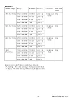
Страница 18: ...mA 4 001 40 00 M 0 01M 2 10 40 01 400 0 M 0 1M 3 5 400 1 4000 M 1M 4 5 500V 0 10 0 500 4 000 M 0 001M 2 10 1mA load 500k 1mA 4 001 40 00 M 0 01M 2 10 40 01 400 0 M 0 1M 2 5 400 1 4000 M 1M 4 5 1000V 0...

Страница 19: ...for positive Minus sign for negative Measurement Rate 2 times per second nominal Low Battery Indication is displayed if battery voltage drops below operating voltage Battery Six 6 1 5V AA batteries F...

Отзывы: