


- 9 -
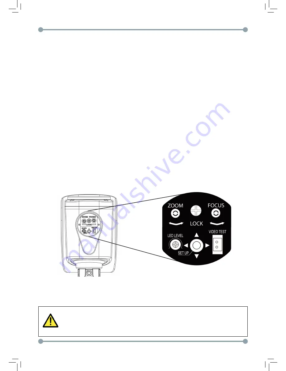
5. Unscrew the service compartment cap to adjust the zoom/focus, LED level, and OSD.
If the service compartment cap is too tight, use the included allen key to loosen it.
•
(Optional) Connect the included video test cable to the
Video Test
connector
to output the video to a BNC test monitor.
•
To adjust the zoom / focus, loosen the middle
Lock
screw with a philipshead
screwdriver. Then turn the
Zoom
and
Focus
screws using the included zoom /
focus adjustment tool or with a small philipshead screwdriver.
•
To adjust the power output to the IR LEDs, use a small philipshead screwdriver
to turn the
LED Level
screw left to decrease the output or right to increase the
output. It is recommended to fine tune the IR level during low light conditions to
determine the best setting.
NOTE:
By default, the IR LEDs are set for maximum output. For short-range installation
environments, it is recommended to turn down the LED level.
•
For details on adjusting the OSD menu, see “How to Set Up the Camera Menu”
on page 11.
NOTE:
OSD menu can also be controlled using a UTC controller (Pelco C protocol;
accessory model number: ACCUTC1).
6. Close the service compartment cap and ensure all camera adjustment screws
are tightened securely. You can use the included allen key to secure the service
compartment cap.
Make sure the rubber seal is on the service compartment cap to ensure the
weatherproof rating of the camera.
Содержание DPB74TLUX
Страница 2: ...2...
Страница 3: ...3...
Страница 13: ...12 Menu Tree...
Страница 14: ...13 Menu Tree Continued...
Страница 15: ...14 Menu Tree...


