FLIR 432-0012-04-00 Скачать руководство пользователя страница 14

 JCU II Power Menu

432-0012-00-10 Version 110

June  2016

14

Powering the JCU II

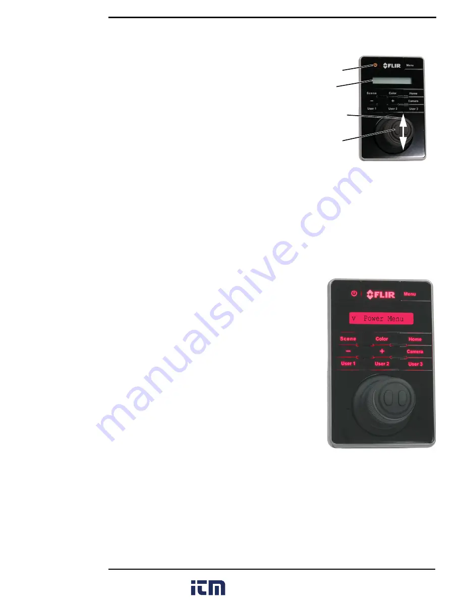
When the JCU II is receiving power, the Power button will 
be lit amber. When the button is pressed for 
approximately three seconds,


the JCU II will turn on and 

search for cameras on the network. 

On the LCD screen, 

Starting

, then 

Searching…

 is 

shown. When a camera is found, the message changes 
to 

Connecting…

, which continues to flash until the 

connection process completes and is replaced by the 
camera ID, such as 

M400

. When more than one camera 

is found on the network, the JCU II attempts to reconnect 
to the last camera it was connected to, or if it has not 
connected to a camera, it will prompt the user to select a 
camera.

JCU II Power Menu

The JCU II LCD screen generally shows the ID of the camera that is connected to the JCU II. The 
various functions are accessed from a set of menus, with each menu entry selectable in the JCU II 
display. When powered on and connected to a camera, pressing and holding the Power button 
causes the JCU II to enter the Power Menu. 

Use the JCU II joystick to scroll up and down (push fore and 
aft), and select an entry by clicking the left joystick button. 
When the JCU II is in the Power Menu mode, the other JCU II 
buttons are disabled. 

In the JCU II display, a down arrow (v) indicates you can access 
additional menu choices by moving the joystick down. An up 
arrow (^) indicates the last menu entry is displayed, and the 
other choices must be accessed by moving the joystick up. A 
double arrow indicates you can move up or down in the menu.

The Power Menu shows the following menu options:

Assign JCU?

JCU Stndby?

Camera Stndby?

System Stndby?

Global Stndby?

Calibrate JCU?

Cancel

Standby States

When finished with the camera, Park the camera from the OSD menu to keep the system ready to 
use at a moments notice on a command from the JCU II. When in Park mode, the system does not 
generate a live video signal. 

To initiate other standby modes, press and hold the Power button. After a brief countdown, the 
Power Menu is shown. Scroll down with the joystick, press the left joystick button to select an 
option from the menu. The menu options available will reflect the available hardware on the 
camera network.

Power

LCD

screen

Select
camera

Scroll up 

or down

www.

.com

[email protected]

1.800.561.8187

Содержание 432-0012-04-00

Страница 1: ...Operator s Manual M400 www com information itm com 1 800 561 8187...

Страница 2: ...ms to prevent EEE waste from arising to encourage reuse recycling and recovery of EEE waste and to promote environmental responsibility In accordance with these regulations all EEE products labeled wi...

Страница 3: ...n Icons 11 Position indicator icons 12 Scene type icons 12 Active Camera Icons 12 On Screen Display OSD Menu 12 M400 System Startup System Startup and Shutdown 13 Park Mode 13 The Bootup Process 13 Po...

Страница 4: ...Surveillance settings 23 Scan Width 23 Scan Speed 23 NMEA 23 Spotlight 24 Image settings 24 Set up 24 Help 24 About 24 Image Settings Menu 24 Polarity IR camera only 25 Stabilization 25 Mirrored view...

Страница 5: ...0 Next Waypoint BWC 30 Radar target TTM 30 Firefighter Mode M400XR only Overview 31 Firefighter Settings Menu 32 Exit Firefighter 32 Select Temperature Units F C 32 Isotherm Thresholds 32 Video Tracki...

Страница 6: ...ion 110 June 2016 6 Image too dark or too light 42 Performance varies with time of day 42 Eastern or Western exposure 42 Multiple Cameras and or JCU IIs on a single network 42 www com information itm...

Страница 7: ...R only Using the on screen display OSD menus for controlling the M400 Helpful reference information such as acronyms parts lists a table of icons and a comparison of model features Additional Referenc...

Страница 8: ...installation or removal of system components Damage to equipment or injury to personnel may result Warning Use of insufficient wire gauge can result in fire Warning The M400 system is not designed to...

Страница 9: ...ermal camera 4x continuous optical zoom HD visible light camera 30x continuous optical zoom High intensity LED spotlight Active gyro stabilization Radar integration to follow specific radar targets NM...

Страница 10: ...e camera position azimuth and elevation and various system settings that have been enabled These symbols are introduced in Thermal Video Display on page 11 and are further explained throughout this ma...

Страница 11: ...y to interpret with some experience The camera automatically optimizes the image to provide the best contrast in most conditions FLIR Systems Inc offers a comprehensive selection of training courses t...

Страница 12: ...mage However you may prefer an image that has more or less contrast than the default one provided and the Scene button provides that type of fine adjustment Active Camera Icons At any given time eithe...

Страница 13: ...e using the system Park the camera from the OSD menu to keep the system ready to use at a moments notice The Bootup Process The bootup process is slightly different depending on whether the system had...

Страница 14: ...the JCU II joystick to scroll up and down push fore and aft and select an entry by clicking the left joystick button When the JCU II is in the Power Menu mode the other JCU II buttons are disabled In...

Страница 15: ...e power it may be connected to a Power over Ethernet PoE switch that has not been powered on or it may be connected to a network switch that does not provide PoE power Troubleshooting Tip If this is t...

Страница 16: ...and left joystick buttons on the top of the joystick are used to select and navigate when in the on screen display menus and the JCU Power Menu Video Tracking M400XR only Use the right joystick butto...

Страница 17: ...s the system on screen display OSD menus In most cases there is no need to modify the factory default configuration settings of the system Refer to M400 System Configuration on page 20 When the OSD me...

Страница 18: ...nvert the thermal camera video polarity for example changing from black hot to white hot Focus Buttons The M400 thermal camera can be focused either manually or automatically The visible light camera...

Страница 19: ...ng Display JCU II Power Menu Home Short Return to home position Home Long Set home to current position Menu Short Display or exit menus Scene Short Cycle through four preset scene settings User 1 Auto...

Страница 20: ...r a few settings revert to the factory default when the system is rebooted Not all options can be used at the same time The way the various options interact is also described in the following sections...

Страница 21: ...ature bands while temperatures below the Isotherm threshold percentage are all in shades of gray After invoking the mode pressing the Menu button will show the InstAlert settings menu The Highlight se...

Страница 22: ...rsion 110 June 2016 22 pressing the Menu button will show the IceAlert settings menu The Highlight setting controls the percentage of the coldest temperatures to display in Blue Green www com informat...

Страница 23: ...0o total Large The camera scan covers 80o to the left and right of center 160o total The default scan width is wide Note The center of the scan pattern is determined by the direction the camera is poi...

Страница 24: ...ff or as Signal Light to control the light When set to Signal Light the UPB will turn on the Spotlight when pressed and turn off the Spotlight when released Image settings See Image Settings Menu on p...

Страница 25: ...rols are actively in use The pan position azimuth icon tilt elevation position icon and the FLIR logo are always displayed Other icons such as home and scene display on the screen only momentarily whe...

Страница 26: ...See User Interface Preferences Menu on page 28 NMEA settings See NMEA Settings on page 30 InstAlert highlight Set the percentage of the highest temperatures in a scene to be displayed in Red Orange A...

Страница 27: ...both the azimuth and elevation should be set to account for variations required during installation so that the icons on the video show the expected angular position of the camera The azimuth directio...

Страница 28: ...arity InstAlert on off IceAlert on off Rearview on off Signal Light Autofocus IR Daylight zoom lock On Off IR digital zoom On Off VIS digital zoom On Off NMEA Data This section describes how to config...

Страница 29: ...message ignoring all other input Note Using the joystick to pan or tilt the camera always takes priority over processing of an NMEA message Each message type has a unique icon associated with it Depen...

Страница 30: ...her briefly or continuously displayed depending on the setting of Icon Display Mode For example while en route the operator could designate a buoy an island or any other landmark as a navigation waypo...

Страница 31: ...camera data as your primary source of information The M400XR system should always be used in conjunction with other appropriate tools Firefighter mode can be activated when either camera is active If...

Страница 32: ...which temperatures in a scene are filled with yellows and reds that represent defined temperature bands The video stream changes dynamically to show the effect of adjustments Selecting the Firefighte...

Страница 33: ...very distinct may sometimes appear less so to the tracker Once a target is being tracked by one of the cameras that camera will continue to provide video to the tracker even if the active camera is c...

Страница 34: ...y While a target is being tracked the system may lose and reacquire the target automatically For example if the target you are tracking is a small boat that is temporarily obscured by a large wave the...

Страница 35: ...a target or acquire a new target press right joystick button Video Tracker Errors If the red cross hairs are seen it means one of two things Communications error with the imx6 In the case of a Comms e...

Страница 36: ...Institute API Application Programming Interface B W Black and White DLTV Daylight TV used to reference visible band cameras EAR Export Administration Regulations EMI Electromagnetic Interference FFC F...

Страница 37: ...OSD on screen display P T Pan Tilt PAL Phase Alternating Line PoE Power over Ethernet SCTE Society of Cable Telecommunications Engineers SDK Software Developer s Kit UPnP Universal Plug and Play Vdc...

Страница 38: ...zoom of cameras to the active payload whenever possible Mirrored View Polarity Color Palette Spotlight continuous Spotlight SOS Spotlight Flash NMEA BWS Message Receiving NMEA messages using Bearing...

Страница 39: ...on the open water during the day Scene Contrast One of four scene presets automatic gain control settings optimized for providing visibility to small moving objects Vertical Stabilization Indicates th...

Страница 40: ...5 in diameter by 46 cm 18 1 in tall Camera Weight 12 22 kg 27 lb depending on the camera model Joystick Size 9 1 X 14 2 X 8 13 cm 3 6 X 5 6 X 3 2 in 7 4 cm 3 in above platform including joystick Joyst...

Страница 41: ...front window of the camera gets water spots wipe it with a clean lens cloth folded in fourths and dampened with fresh water Video not switching between thermal and visible On dual payload models the...

Страница 42: ...n everything may be coated with dew Under these conditions it may be difficult for the camera to show the temperature the object itself rather than of the water coating Eastern or Western exposure Whi...

Страница 43: ...432 0012 00 10 Rev 110 June 2016 www com information itm com 1 800 561 8187...

Отзывы: