FAD-40 Technical Manual, Rev.2.1.0; February 2022
Page 33 of 55
6.6. Profibus and Profinet Data Structure (for FAD-40Px only)
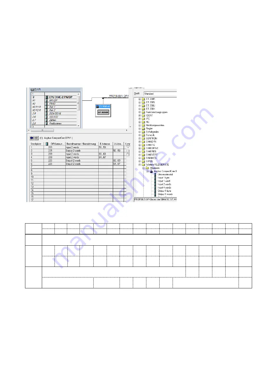
Hardware Configuration Hint
To install the FAD-40PB or FAD-40PN into the PLC Hardware Configuration use the GSD (GSDML) file, which
is on Product DVD or under www.flintec.com to create
exactly
the following memory structure:
1. Input 2 Words
2. Output 2 Words
3. Input 2 Words
4. Input 2 Words
5. Output 2 Words
6. Output 2 Words
FAD-40Px Output to PLC Input
Dword
D31 D30 D29 D28
D27 D26 D25 D24 D23 D22 D21 D20 D19 D18 D17 D16
D15 D14 D13 D12
D11 D10
D9
D8
D7
D6
D5
D4
D3
D2
D1
D0
1st
Dword
Reserved
2nd
Dword
W31
MSB
W30 W29 W28 W27 W26 W25 W24 W23 W22 W21 W20 W19 W18 W17 W16
W15 W14 W13 W12 W11 W10
W9
W8
W7
W6
W5
W4
W3
W2
W1
W0
LSB
3rd
Dword
Not in use
I/O2
in
I/O3
in
I/O3
out
I/O2
out
I/O1
out
Error codes of converter
Not in use
Op.
mode
Zero
range
Gross
Net
MD
Read command response
Cmd
Flag
FAD-40Px Output to PLC Input 2
nd
Dword
The 2
nd
Dword
contains the weight value respective the calibration information according to the “read command
response” (Refer to PLC Output to FAD-40Px Input 3rd Dword).


