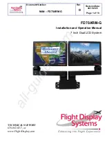
Flight Display Systems FD70ARM-G Скачать руководство пользователя страница 2


Document Number: 
 

MAN – FD70ARM-G


Rev: 


D


Revision Date: 

04/11/2011 


Page 2 of 18


FD70ARM-G 

7" Dual LCD System 


© 2006 Flight Display Systems. All Rights Reserved.  


Flight Display Systems


1765 Grassland Parkway 
Alpharetta, GA  30004 
678-867-6717 Phone 
678-867-6742 Fax 

[email protected]


www.flightdisplay.com


For the most current copy of all product manuals, please visit our website at 

www.flightdisplay.com 

All manuals and user guides at all-guides.com

Содержание FD70ARM-G

Страница 1: ...v D Revision Date 04 11 2011 Page 1 of 18 FD70ARM G Installation and Operation Manual 7 Inch Dual LCD System TECHNICAL SUPPORT 678 867 6717 or www FlightDisplay com All manuals and user guides at all guides com a l l g u i d e s c o m ...

Страница 2: ...y Systems All Rights Reserved Flight Display Systems 1765 Grassland Parkway Alpharetta GA 30004 678 867 6717 Phone 678 867 6742 Fax sales flightdisplay com www flightdisplay com For the most current copy of all product manuals please visit our website at www flightdisplay com All manuals and user guides at all guides com ...

Страница 3: ...tallation Instructions 5 1 Power 5 Wiring Instructions 7 1 S Video Composite Audio Wiring 7 2 VGA Wiring 8 3 Power Ground Wiring 9 4 Power Video 10 Operations Instructions 13 1 Button Control 13 Technical Drawing 14 Troubleshooting 15 Technical Support 16 Instructions for Continued Airworthiness 17 Warranty 17 Log of Revisions 18 All manuals and user guides at all guides com ...

Страница 4: ... components The milled aluminium arms represent the evolution of several design enhancements for an optimum removable mounting solution As a dual LCD system the FDARM G was designed to be used with a base receptacle the FDBASE 2G The following bases can be used FDBASE FL FDBASE 1G FDBASE Ver SDI and the FDBASE The 7 Widescreen LCDs utilize a state of the art digital video decoding chipset for the ...

Страница 5: ...sub Standard Video Input 2 Composite Video Video Type Supported NTSC PAL Screen Control On Screen Display Menu Remote Control IR included Materials Aluminum DO 160 Testing Section 21 Category B Installation Instructions All cabin entertainment equipment such as the FD70ARM G should be installed on a non essential bus and have a dedicated circuit breaker It is a requirement that a switch be install...

Страница 6: ...Document Number MAN FD70ARM G Rev D Revision Date 04 11 2011 Page 6 of 18 All manuals and user guides at all guides com a l l g u i d e s c o m ...

Страница 7: ...s video and audio purposes is PIC 75 Ohm Coax P N V76261 This is a lightweight flexible and low signal loss cable which meets FAA flammability requirements of FAR 23 1359 d FAR 25 853 a and FAR 25 869 a 4 Similar aviation coaxial cable can be used from other vendors as well Some aircraft are prone to AC noise we recommend adding to the composite source a 75 Ohm video isolation transformer such as ...

Страница 8: ...pose is ECS P N 453005 This is a single shielded cable containing 5 separate coaxial cables color coded to match the functions of the wires We recommend coax cables be terminated using solder sleeve coaxial cable terminators such as Raychem Part Number CWT 4174 W122 5 9 All manuals and user guides at all guides com ...

Страница 9: ...8VDC power system and a total of 50 feet of wire between the circuit breaker monitor and ground Example 22awg wire has 16 2 Ohms per 1000 feet this equates to 81 Ohms for 50 feet 1 5 Amps of current on 81 Ohms will drop 1 22 Volts Resistance of Wire Type M22759 16 Gauge Gauge AWG OHMS 1000 24 26 20 22 16 20 20 9 88 16 4 81 12 2 02 10 1 26 8 701 Also use short heavy gauge wire and a clean tight con...

Страница 10: ...2 12 28VDC Ground 3 N C 4 Composite Video 1 Signal 5 Composite Video 1 Shield 6 N C 7 Composite Video 2 Signal 8 Composite Video 2 Shield 9 Red Video Pin 1 on Standard VGA 10 Green Video Pin 2 on Standard VGA 11 Blue Video Pin 3 on Standard VGA 12 Red Ground Pin 6 on Standard VGA 13 Green Ground Pin 7 on Standard VGA 14 Horizontal Sync Pin 13 on Standard VGA 15 Vertical Sync Pin 14 on Standard VGA...

Страница 11: ...quivalent Pin Number Description 1 28VDC Power 2 28VDC Ground 3 N C 4 N C 5 N C 6 N C 7 N C 8 N C 9 Video Red T568B Cat5 Pin 1 10 Video Red T568B Cat5 Pin 2 11 Video Blue T568B Cat5 Pin 3 12 Video Blue T568B Cat5 Pin 6 13 Video Green T568B Cat5 Pin 5 14 Video Green T568B Cat5 Pin 4 15 Video Ground T568B Cat5 Pin 8 Note Cat5 Pin 7 is not used All manuals and user guides at all guides com a l l g u ...

Страница 12: ...ceptacle Supplied mounted in FDBASE Ver SDI Connector P N Conec 3005W1SM99A10X Coax Contact P N Conec 132J30029X for use with RG179 Other cable type contacts available from Conec MATING FACE Pin Number Description 1 28VDC Power 2 28VDC Ground 3 N C 4 N C A1 HDSDI IN All manuals and user guides at all guides com ...

Страница 13: ...he video output from the FD70ARM G using the video source select switch on the LCD monitor or remotely throughout the cabin with the included IR remotes Monitor Control Buttons BUTTON FUNCTION DESCRIPTION 1 POWER Press to turn the monitor on if currently off Hold to turn the monitor off 2 SOURCE Press to switch between sources 3 UP Press to increase the value of a menu item 4 DOWN Press to decreas...

Страница 14: ...Document Number MAN FD70ARM G Rev D Revision Date 04 11 2011 Page 14 of 18 Technical Drawing All manuals and user guides at all guides com ...

Страница 15: ...commended Snow or Sweeping Lines Lines that slowly sweep up and down are a result of AC noise This AC noise can be generated by a power cart on the aircraft Take the power cart off of the aircraft Be careful of inverter wiring which can also cause noise Stand off the wires if necessary If snow or sweeping lines persist it is possible that the ground is at an incorrect point in the aircraft Try mov...

Страница 16: ...our Product Support representatives at 678 867 6717 Flight Display Systems 1765 Grassland Parkway Alpharetta GA 30004 Phone 678 867 6717 Fax 678 867 6742 Email sales flightdisplay com For further product information technical data and sample wiring diagrams please click on the Dealers section of our web site at www flightdisplay com All manuals and user guides at all guides com a l l g u i d e s c...

Страница 17: ...MA number will be issued at that time Flight Display Systems will upon receipt of the failed hardware remanufacture or replace the unit at our discretion Flight Display Systems will pay Ground Shipping charges for warranted items Charges for express shipment will be the responsibility of the sender This warranty is not transferable Any implied warranties expire at the expiration date of this warra...

Страница 18: ...ev Date Page Description A 09 12 2007 B 02 26 2009 2 10 Updated specifications warranty info C 01 08 2010 1 2 5 6 7 11 Update picture specs pinout monitor buttons assembly drawing D 04 11 2011 8 Added pinout for FD70ARM G Ver SDI updated VGA wiring All manuals and user guides at all guides com ...

Отзывы: