Flexxaire FX 2000 Series Скачать руководство пользователя страница 12

Page 2-4

01523r7.wpd

Section 2 - Hydraulic Fan Group

June 14, 2007

Printed in Canada

2.2 INSTALLATION

The following describes the removal of an existing fan
and the installation of a Flexxaire

®

 FX Fan assembly

onto your application.

2.2.1.1. Existing Fan Removal

A.

   Gain access to engine compartment.

B.

   Remove fan guards and safety equipment to get 

      access to existing fan.

NOTE:

Only  remove  engine components that
interfere  with  the  installation of the fan.
Removal of other components may create
unnecessary work.

C.

   Remove belt(s).

D.

  Attach hoisting device to remove existing fan       

assembly. 

NOTE:

When lifting fan assembly, use a proper
hoist  to  avoid  personnel  injury  and
damaging equipment.

E.  

 Loosen and remove bracket mounting bolts.

F.  

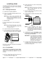
 Lift fan assembly from engine compartment onto 

     floor or another desired location. Refer to 

Figure 2.

Figure 2

G.

 Clean mounting surface of engine for the installation

of the Flexxaire

®

 fan.

2.2.1.2. Fan Installation

Your  Flexxaire

®

  Fan  is  shipped with the fan blades

unattached. After installing the hub assembly onto the
machine  the  fan  blades  are attached to the hub
assembly.

A.

Remove shipping straps and anchors from around
the hub assembly and shipping crate.

B.

Attach hoisting device to remove hub assembly
from shipping crate.

NOTE:

When lifting hub assembly, use a proper
hoist  to  avoid  personal  injury  and
damaging equipment.

C.

Lower and align hub assembly with the mounting
holes on the engine block.
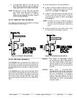
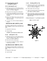
D.

Install and tighten mounting brackets bolts. Refer
to 

Figure 3

.

Figure 3

NOTE:

In  some  installations, bolts may be
replaced  by  studs. These are provided
where necessary. Always use Grade 8 or
better bolts and/or studs when attaching
the fan bracket.

E.

Install fan belts; however, 

do not tighten

. Always

ensure there is adequate adjustment to keep the
fan belts tight over their lifetime.

IMPORTANT:

Some applications use a different
pulley  diameter than the OEM
pulley in fan designs. Ensure that
the belt(s) fit(s). If it does not,
determine  the  correct  size  and
record it for future reference.

F.

As required, the fan pulley may be moved in order
to facilitate access to hydraulic fitting or to tighten
fan bracket mounting bolts.

Содержание FX 2000 Series

Страница 1: ...c Manual 01523r7 wpd Page 0 1 FLEXXAIRE ENGINE TEMPERATURE CONTROL SYSTEMS FX 2000 FAN SERIES HYDRAULIC PITCH CONTROL G IF BOX IS CHECKED REFER WITHIN FRONT COVER PAGE OF THIS MANUAL FOR SPECIAL INSTR...

Страница 2: ...Page 0 2 01523r7 wpd Hydraulic Manual June 14 2007 Printed in Canada...

Страница 3: ...7 wpd Page 0 3 Table Of Contents SECTION 1 GENERAL INFORMATION 1 1 1 1 INTRODUCTION 1 3 1 2 IMPORTANT SAFETY INFORMATION 1 3 1 3 FAN OVERVIEW 1 4 SECTION 2 HYDRAULIC FAN GROUP 2 1 2 1 INTRODUCTION 2 3...

Страница 4: ...Page 0 4 01523r7 wpd Hydraulic Manual June 14 2007 Printed in Canada...

Страница 5: ...INFORMATION SECTION 1 GENERAL INFORMATION 1 1 1 1 INTRODUCTION 1 3 1 2 IMPORTANT SAFETY INFORMATION 1 3 1 2 1 Protective Equipment 1 3 1 2 2 Pressurized Items 1 3 1 2 3 Hot Fluids and Parts 1 3 1 2 4...

Страница 6: ...Page 1 2 01523r7 wpd Section 1 General Information Overview June 14 2007 Printed in Canada...

Страница 7: ...epair on this product until you have read and understand the operation lubrication maintenance and repair information Please contact Flexxaire or their approved dealer for any information that you may...

Страница 8: ...ines tubes or hoses because leaks can cause fires H Tighten fasteners to the correct torque Make sure all heat shields clamps and guards are installed correctly to avoid excessive heat vibration or ru...

Страница 9: ...ecting A Hydraulic Source 2 6 2 2 2 3 Control Kit Information 2 6 2 2 2 4 Hydraulic Valve Installation 2 7 2 2 2 5 Electrical Installation 2 7 2 2 2 6 Hydraulic Control Set Up 2 8 2 2 2 7 FX Fan Opera...

Страница 10: ...Page 2 2 01523r7 wpd Section 2 Hydraulic Fan Group June 14 2007 Printed in Canada...

Страница 11: ...sitions respectively 2 1 1 External Identifiable Components The Hydraulic Fan Assembly can be identified by several external major components in Figure 1 Use this diagram for terminology and component...

Страница 12: ...the fan blades unattached After installing the hub assembly onto the machine the fan blades are attached to the hub assembly A Remove shipping straps and anchors from around the hub assembly and shipp...

Страница 13: ...gh the upper holes in the blade caps and blades Tighten the blade caps to the blades using the supplied 1 4 NC flanged lock nuts Regular hex head bolts with washers may be supplied in place of flange...

Страница 14: ...Differential Pressure Source Pressure minus Return Pressure must meet or exceed the minimum pressure requirement D Avoid hydraulic systems with high pressure spikes E The hydraulic source must have ac...

Страница 15: ...ic system being used D Attach a hydraulic line from ports 2 and 4 of the fan valve body to the fittings on the fan Figure 9 2 Position Solenoid Valve Figure 10 3 Position Solenoid Valve 2 2 2 5 Electr...

Страница 16: ...equired Install additional switches parallel to the engine temperature switch as shown in Figure 11 Contact Flexxaire for ordering additional temperature switches E Make wiring connections as per Figu...

Страница 17: ...ostat is required If this is the only location for the temperature switch then a switch with a lower temperature rating is required Contact your local dealer or Flexxaire NOTE By adding a jumper to th...

Страница 18: ...n optional oil level check is recommended for every 1000 operational hours or if there is reason to believe the fan is losing oil The fan contains MOBIL Synthetic SHC629 oil Refer to Table 2 below for...

Страница 19: ...ION Low oil level may indicate a leak 2 3 2 2 Adding Oil To Fan A Rotate the hub until one of the oil drain plugs is at the 12 00 position and the other at the 2 00 position As indicated in Figure 13...

Страница 20: ...ves air away from the engine go to B A Are the blades mounted with the concave surface towards the engine G G B Are the blades mounted with the concave surface towards the radiator G G Are blade bolts...

Отзывы: