background image

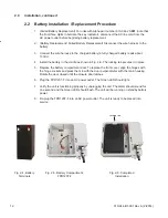
Fig. 2-4, Battery 

Terminals

Fig. 2-6, Completed 

Installation

2.0 Installation, 

continued 

2.2  Battery Installation / Replacement Procedure

1.  (Failed Battery Replacement) For units with Alpha part number 010-344-20-

001

 (note that 

the final three digits in bold are the key indicator), disconnect the AC line cord from the 

AC power outlet before beginning battery replacement.

2.  (Battery Replacement / Failed Battery Replacement) Disconnect the wire harness to the 

battery. 

3.  Connect the wire harness to the charged battery (a fully charged battery reads about 

13Vdc).

4.  Install the battery in the cradle as shown in Fig. 2-6. The locking tab secures it in place.

5.  Replace the battery compartment door. To replace the front cover, align the hinges with 

the hinge sockets and press them in with the door perpendicular with the main housing. 

Rotate the door closed until the closure door latches.

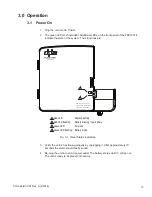
6.  Plug the FPR1207-F into an AC power outlet. The Green LED should light.

7.  Verify the unit is functioning properly by unplugging the unit. The alarm should sound for 

one second and the Green LED should flash. The unit will be running on standby battery 

power.

8.  Re-plug the FPR1207-F into an AC power outlet. The unit is ready to be placed into 

service.

Fig. 2-5, Battery Compartment, 

FPR1207-F 

The unit will not yet be on unless Battery Emergency Use button is pushed.

Locking tab

010-344-B1-001 Rev. A (2/2014)

12

Содержание FPR1207-F

Страница 1: ...FlexPoint FPR1207 F Technical Manual FlexPoint FPR1207 F 7W UPS Effective February 2014...

Страница 2: ...Power Alpha Technologies...

Страница 3: ...if installed or operated in an unapproved manner or improperly maintained Operator is cautioned to review the drawings and illustrations contained in this manual before proceeding If there are questio...

Страница 4: ...10 2 1 Installation and Connection 10 2 2 Battery Installation Replacement Procedure 12 3 0 Operation 13 3 1 Power On 13 3 0 Operation continued 14 3 2 Audible Alarms and Visual Indicators 14 3 3 Batt...

Страница 5: ...Unit Dimensions 10 Fig 2 2 FPR1207 F Output Cables and Connections 11 Fig 2 3 Function List Inside Lid of Enclosure 11 Fig 2 4 Battery Terminals 12 Fig 2 5 Battery Compartment FPR1207 F 12 Fig 2 6 Co...

Страница 6: ...lowing symbols have been placed throughout this manual Where these symbols appear use extra care and attention A NOTE provides additional information to help complete a specific task or procedure NOTE...

Страница 7: ...ttery capacity remains the 12Vdc supply to the ONT will be interrupted while the unit enters a sleep mode conserving the remaining capacity for emergency calls Interruption of the 12Vdc supply to the...

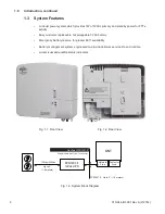
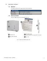
Страница 8: ...for greater E911 availability Battery management system engineered to provide optimum service life and runtime Local visual and audible status indicators Fig 1 1 Front View Fig 1 2 Rear View Fig 1 3...

Страница 9: ...ear Warranty AX LONGBAT 7 Battery 7 2AH AGM 3 year Warranty AX LONGBAT 8 Battery Longlife 8Ah AGM 3 year Warranty 1 0 Introduction continued 1 4 Options The FlexPoint FPR1207 F supports three models o...

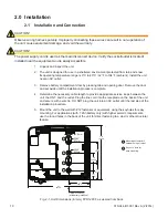
Страница 10: ...ntil the installation process is complete 4 Determine the necessary cable length to provide appropriate service loops between the unit the ONT and the outlet Plug the line cord into the receptacle on...

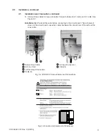
Страница 11: ...e circuit board caused by contact between the closed door of the unit and the coax cable 2 0 Installation continued 2 1 Installation and Connection continued Fig 2 2 FPR1207 F Output Cables and Connec...

Страница 12: ...Install the battery in the cradle as shown in Fig 2 6 The locking tab secures it in place 5 Replace the battery compartment door To replace the front cover align the hinges with the hinge sockets and...

Страница 13: ...fter approximately 10 seconds the alarm should briefly sound 4 Re plug the unit into an AC power outlet The battery status LED 1 will go out The unit is ready to be placed into service Fig 3 1 Visual...

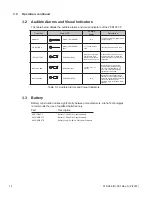
Страница 14: ...ndition normal AC powers load charges battery ON BATTERY Battery LED GREEN flash 1 1s beep on loss of AC Input fails battery powers load LOW BATTERY RED LED blinking When AC is available audible alarm...

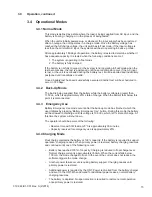
Страница 15: ...c which is approximately 25 state of charge When the battery falls below this point it is disconnected 3 4 3 Emergency Use Battery Emergency Use mode occurs after the back up mode has finished which t...

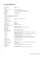
Страница 16: ...arm Suppresses the audible alarm for 24 hours Battery Emergency Use Accesses reserve battery capacity AGENCY COMPLIANCE Safety US NRTL certified to UL CSA 60950 1 Ed 2 ITE Pollution Degree 2 Overvolta...

Страница 17: ......
Страница 18: ...Thorley Bishop s Stortford Hertfordshire CM22 7PA United Kingdom Tel 44 1279 501110 Fax 44 1279 659870 Alphatec Ltd 339 St Andrews St Suite 101 Andrea Chambers P O Box 56468 3307 Limassol Cyprus Tel...

Отзывы: