SA-FOM4
TM
(
F
i
b
e
r
O
p
t
c
a
l
M
u
x
)
I
n
s
o
d
D
V2.0
January 2003
Страница 1: ...M4 TM F Fi ib be er r O Op pt ti ic ca al l M Mu ul lt ti ip pl le ex xe er r I In ns st ta al ll la at ti io on n a an nd d O Op pe er ra at ti io on n D De es sc cr ri ip pt ti io on n V2 0 January...
Страница 2: ......
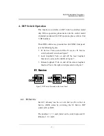
Страница 3: ...K NELLB 5 3 3 E1 REMOTE LOOPBACK E1RLB 5 4 DIP SWITCH OPERATION 7 4 1 E1 SERVICE 7 4 2 E1 LOCAL LOOPBACK 8 4 3 E1 REMOTE LOOPBACK 8 5 CID CONSOLE OPERATION 9 5 1 CID CONNECTION 9 5 2 CID MAIN MENU 10...
Страница 4: ...SA FOM4 Installation Description SA FOM4 2 0 20030102 6 ELECTRIC POWER AND GROUND INSTALLATIONS 21 7 SYSTEM CONNECTIONS 22 8 ALARM OUTPUT PORT 25 ii...
Страница 5: ...tters Multi meter RJ 45 E1 connector cable RS232 Connector cable Power cable AWG 8 Single bone One cable each for red and black Ground cable AWG 14 Single bone One green cable FC PC Patch cord FC PC c...
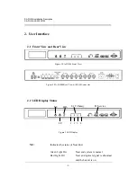
Страница 6: ...re 1 SA FOM4 Front View Figure 2 SA FOM4 Rear View w RJ 45 Connector 2 2 LED Display Status NE FE LOS E1 Tributary 1 2 3 4 E1 Service Figure 3 LED Display NE Indicates the status of Near End Green Lig...
Страница 7: ...optical interface is in normal status Red Light On The optical interface has lost signal and buzzer is on Red Light Blinking SA FOM4 is performing Near End Local Loopback E1 There are four E1 tributa...
Страница 8: ...point of signal connection or equipment Notice Please notice that while performing loopback testing either local loopback or remote loopback the corresponding E1 tributary should be set to Out of Ser...
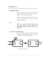
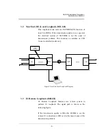
Страница 9: ...s function is available on CID Consol controlled model only NEAR END FAR END 4 E1 EIO OPTICAL OPT 4 E1 EIO OPTICAL OPT NEAR END LOCAL LOOPBACK NELLB Figure 5 Near End Local Loopback Diagram 3 3 E1 Rem...
Страница 10: ...0030102 Note The E1RLB is set by the local CID The system will malfunction if the E1RLB is set by remote system simultaneously NEAR END FAR END 4 E1 EIO OPTICAL OPT 4 E1 EIO OPTICAL OPT E1 REMOTE LOOP...
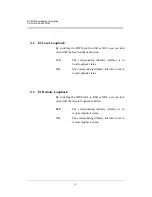
Страница 11: ...nd off the local loopback function Locates on the middle of Figure 7 3 Remote loopback Turn on and off the remote loopback function This is the right switch presented on Figure 7 E1 Service E1 Service...
Страница 12: ...g tributary interface is in local loopback status NLL The corresponding tributary interface is not in local loopback status 4 3 E1 Remote Loopback By switching the DIP Switch to RLB or NRL user can tu...
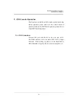
Страница 13: ...ase make sure the control model of product purchased For DIP Switch operation please refer to Unit 4 DIP Switch Operation 5 1 CID Connection Connect CID port with RS 232 to the com port of PC SA FOM4...
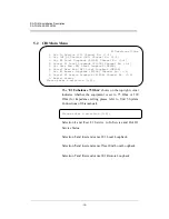
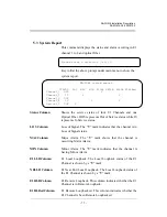
Страница 14: ...LB Channel No 1 4 8 Cancel E1 Remote Loopback E1RLB Channel No 1 4 0 Report status Please enter a selection 0 9 The E1 Unbalance 75 Ohm shows on the top right corner indicates whether the equipment is...
Страница 15: ...rvice status while IS represents In Service status LOS Column Loss of Signal The V mark indicates that the channel is in Loss of Signal status MAJ Column Major Alarm The V mark shows that the channel...
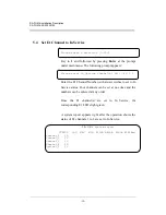
Страница 16: ...e Channel s No 4 3 2 1 Enter the E1 Channel Number s that user wishes to set to In Service status Four channels can be set at one time and the numbers can be entered at any order Once the E1 channel s...
Страница 17: ...hannels 2 and 4 are set to Out of Service STATUS LOS MAJ MIN IS OOS IS OOS IS key under main menu The following prompt appears Enter the E1 Channel Number s that user wishes to set to Out of Service s...
Страница 18: ...al Loopback the STATUS LOS MAJ MIN OOS V OOS OOS V OOS key at the prompt Please enter a selection under main menu The following prompt appears If user is sure to perform the loopback press at the prom...
Страница 19: ...order STATUS LOS MAJ MIN Channel_1 OOS OOS V OOS OOS IS key at the prompt Please enter a selection under main menu The following prompt appears Enter the E1 Channel Number s that user wishes to cancel...
Страница 20: ...r Y or y is pressed at this blinking red Enable NE Local Loopback STATUS LOS MAJ MIN Channel_1 OOS V OOS V OOS V OOS V OOS key at the prompt Please enter a selection under main menu The following prom...
Страница 21: ...tting is not allowed Please enter a selection 0 9 6 Key in 5 and press the Enter Cancel E1 STATUS LOS MAJ MIN Channel_1 OOS OOS OOS OOS IS key at the prompt Please enter a selection under main menu Th...
Страница 22: ...nu The following prompt appears Do you want to enter the MAINTAIN Status Y N any key Y If user is sure to perform the loopback press at the prompt prompt Otherwise press any key to return to the main...
Страница 23: ...he above report is shown on the local site and the report STATUS LOS MAJ MIN OOS V OOS V OOS OOS IS shown on the remote site would appear as the following SA FOM4 system report E1LLB NELLB E1RLB E1RLB...
Страница 24: ...s cancelled STATUS LOS MAJ MIN OOS OOS V OOS OOS IS 5 11 Cancel E1 Remote Loopback key at the prompt Please enter a selection under main menu The following prompt appears Enter the E1 Channel Number s...
Страница 25: ...is used as a back up power source AC Power Supply Connect an AC power outlet with a supply voltage of either 110 or 220 VAC to the AC power connector in the rear panel AC IN Figure 8 DC Power Input P...
Страница 26: ...rs the positions are shown in Figure 10 OPTICAL INTERFACE OUT IN Figure 10 Optical Interface Port Switch the impedance to 75 or 120 according to equipment specification 75 120 Figure 11 75 120 Impedan...
Страница 27: ...y 1 2 Pin1 Pin2 Pin3 Pin4 1 2 6 7 8 1 2 6 7 8 1 2 6 7 8 1 2 6 7 8 RJ 45 Female Connector 3 4 Tx Ring Tx Tip Rx Ring Rx Tip Tx Output Rx Input Line Interface Pin Assignment 3 4 5 3 4 5 3 4 5 RxTip4 RxR...
Страница 28: ...cting to a terminal or PC The supervisory port utilizes male plug DB9 connector The port is configured as DTE devices Figure 14 shows the pinout and signals for the CID Console port connector unused u...
Страница 29: ...tion Description SA FOM4 2 0 20030102 8 Alarm Output Port The Alarm output port uses NELTRONTM 3 96mm center wire to board connector as shown in Figure 6 Alarm Contact M C M A O I J M N Figure 15 Alar...