-12-
remove the battery pack before performing
any assembly.
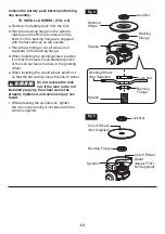
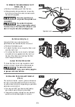
TO INSTALL A WHEEL: (FIG. 4-5)
a. Remove the battery pack from the tool.
b. Place the backing flange on the spindle,
making sure that the flat surfaces on the
bottom of the backing flange are engaged
with the flat surfaces on the spindle.
c. Place the grinding or cut-off wheel (not
supplied) on the backing flange.
d. When installing the grinding wheel, position
it so that the raised, small-diameter portion
of the lock nut faces the hole in the grinding
wheel.
e. When installing the cut-off wheel, position it
so that the flat surface faces the cut-off wheel.
WARNING
Do not reverse the lock
nut. If the lock nut is not
installed properly, the wheel cannot be
properly tightened, and serious injury can
result.
f. While pressing the spindle lock, tighten
the lock nut by turning it clockwise with the
wrench supplied.
Fig. 5
Lock Nut
Backing Flange
Spindle
Cut-off Wheel
(Not Supplied)
Cut-off Wheel
Guard
(Model FT311,
Not Supplied)
Fig. 4
Lock Nut
Backing
Flange
Grinding
Wheel
Spindle
Lock Nut
Backing
Flange
Grinding Wheel
(Not Supplied)
Spindle


