FTB 205 Coupling Transformer - Installation Instructions
7904505 Rev1
Page
2
of
2
Instructions
1.
Open the FTB 205 enclosure door to power off the unit. Allow the High Voltage to bleed off.
2.
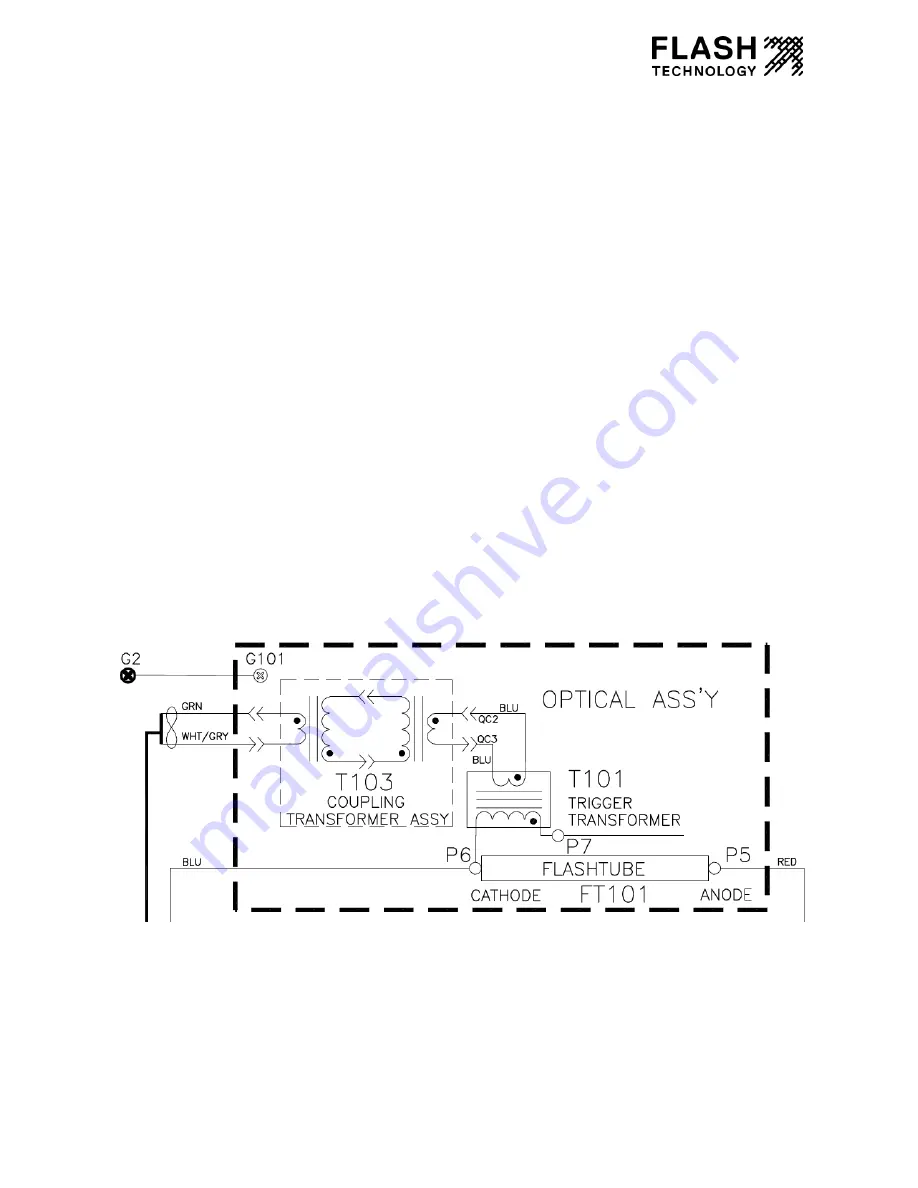
Locate the T101 Trigger Transformer Assembly on the left side of the door-mounted Optical
assembly. Disconnect the two blue terminals connecting the 7-Turn Winding to the White/Gray
and Green wires. Cut wire ties as necessary to free the terminals.
3.
Orient the FTB 205 Coupling Transformer Assembly plate as shown in photo with the coupling
transformers pointed down and the two blue wires with wire extensions on right.
4.
Position the plate in the location shown on top of the Optical Assembly. Do not install screws at
this time.
5.
Connect the 2 blue terminals from the left 7-Turn Winding to the 2 blue terminals from the T101
Trigger Transformer Assembly.
6.
Connect the 2 blue terminals from the right 7-Turn winding to the 2 blue terminals from the
White/Gray and Green wires disconnected previously. Position all wires under the plate.
7.
Mount the plate using a #2 Screwdriver and the 4 – 6-32 X 1/2 PPH screws supplied with kit.
8.
Install wire ties to secure wires as needed.
9.
Install new Info Card onto back of Optical Assembly
10.
Power on and verify correct operation by testing in all modes and confirming no alarms.
FTB 205 Optical Assembly Wiring Diagram with T103 Coupling Transformer Assembly Installed


