
LED PAR 64 7x10W RGBW 4in1 ABS F7000300
www.flash-butrym.pl
3
4
INSTALLATION
After removing the packaging, check if the device was not damaged during transport. Before connecting to
the mains, make sure that the device is securely mounted. The manufacturer is not responsible for damage
caused by unstable mounting.
Ensure proper connection to the mains and proper grounding. Make sure that the electrical parameters are
consistent with device requirements. All activities, including connecting the device to the mains must be
performed by qualified personnel.
5
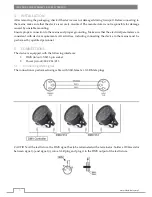
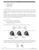
CONNECTIONS
The device is equipped with the following interfaces:
1.
DMX (in/out): XLR 3-pin socket
2.
Power (in/out): IEC C14/C13
5.1
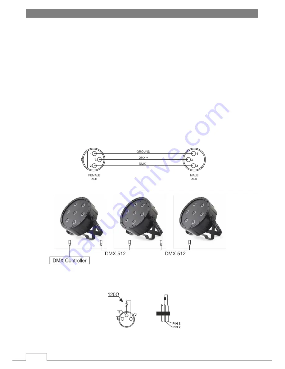
Connecting DMX signal
The connection is performed using cable with XLR-female -> XLR-Male plugs.
CAUTION: At the last fixture, the DMX signal has to be terminated with a terminator. Solder a 120Ω resistor
between signal (-) and signal (+) into a XLR plug and plug it in the DMX output of the last fixture.


