Fixturlaser GO Pro Скачать руководство пользователя страница 21

Fixturlaser GO Pro Manual 2

nd

 edition 

6.5 


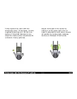
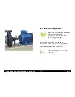
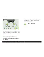
Firmly tighten the chain with the 

tensioning screw. If necessary, use the 

supplied tensioning tool. Do not over-

tighten. If the shaft diameter is too 

large the chains can be extended with 
extension chains (optional). 


Adjust the height of the sensor by 

sliding it on the posts until a line of 

sight is obtained for both lasers. Secure 

its position by locking both clamping 

devices on the back of both units.  


Содержание GO Pro

Страница 1: ...MANUAL Fixturlaser GO Pro user s...

Страница 2: ......

Страница 3: ...4 1 Main Menu 5 1 Shaft Alignment Horizontal Machines 6 1 Shaft Alignment Vertical Machines 7 1 Machine Defined Data 8 1 Softcheck 9 1 Target Values 10 1 Memory Manager 11 1 Global Settings 12 1 Disp...

Страница 4: ...Fixturlaser GO Pro Manual 2nd edition September 2011...

Страница 5: ...purpose of this manual is to guide you through the different procedures and operations of the hardware and software Since machine installations and setups are often different from each other we have...

Страница 6: ...in the system is the property of Elos Fixturlaser AB any copying or redistribution is strictly prohibited Modifying disassembling reverse engineering or decompiling the system or any part thereof is s...

Страница 7: ...875 Fixturlaser GO Pro Manufacturer s name address telephone fax no Elos Fixturlaser AB Box 7 SE 431 21 M lndal Sweden Tel 46 31 7062800 Fax 46 31 7062850 The following standards and or technical spec...

Страница 8: ...es Operation is subject to the following two conditions 1 this device may not cause harmful interference and 2 this device must accept any interference received including interference that may cause u...

Страница 9: ...o the equipment Do not disassemble modify or use the equipment in other ways than explained in the operating instructions Fixturlaser will not accept any liability for such use LASER PRECAUTIONS Fixtu...

Страница 10: ...11 POWER SUPPLY Fixturlaser GO Pro is powered by three 1 5V LR 14 C Alkaline batteries or by corresponding 1 2V NiMH HR 14 Rechargeable Nickel Metal Hydride cells Only use high performance alkaline ba...

Страница 11: ...se of batteries in accordance with local regulatory guidelines if in doubt contact your local sales representative WIRELESS TRANSCEIVER The GO Pro system is fitted with Bluetooth wireless transceivers...

Страница 12: ...Fixturlaser GO Pro Manual 2nd edition 3 4...

Страница 13: ...etector and laser window surfaces which should be cleaned with alcohol Do not use paper tissue which can scratch the detector surface Do not use acetone For the best possible function the laser diode...

Страница 14: ...Fixturlaser GO Pro Manual 2nd edition 4 2 The chains on the V block fixtures are delivered dry If the system is used in highly corrosive environments the chains should be oiled...

Страница 15: ...nt programs for specific purposes Press the red On Off button to start the system and the Main Menu appears Here you can select the program that you want to use In the Main Menu you will also find the...

Страница 16: ...edition 5 2 APPLICATION PROGRAMS Shaft Alignment Horizontal Machines Shaft Alignment Vertical Machines Machine Defined Data MEMORY MANAGER Memory Manager SYSTEM FUNCTIONS Global Settings Off Wireless...

Страница 17: ...n the system The Fixturlaser GO Pro system has two measuring units that are placed on each shaft by using the fixtures supplied with the system After rotating the shafts into different measuring posit...

Страница 18: ...e there any restrictions for mounting the measuring system Is it possible to rotate the shafts What shim size is needed Before setting up the alignment system on the machine check the machine foundati...

Страница 19: ...Fixturlaser GO Pro Manual 2nd edition 6 3 Check coupling and shaft run out Pipe work strain Coarse alignment Check coupling gap axial alignment...

Страница 20: ...sensor marked S on the stationary machine The sensors shall be assembled on their V block fixture and placed on each side of the coupling Hold the V block fixture upright and mount it on the shafts of...

Страница 21: ...ed tensioning tool Do not over tighten If the shaft diameter is too large the chains can be extended with extension chains optional Adjust the height of the sensor by sliding it on the posts until a l...

Страница 22: ...but this might be necessary when measuring at long distances NOTE Make sure that the adjustment screw is secured with the locking nut after adjustment Connect the cables from the wireless communicatio...

Страница 23: ...G THE PROGRAM Start the program by selecting the Horizontal Shaft Alignment icon in the Main Menu and press OK When the program is started a tolerance table will be displayed first Select tolerance an...

Страница 24: ...be helpful if no tolerances are specified The suggested tolerances can be used as a starting point for developing in house tolerances when the machinery manufacturer s recommended tolerances are not...

Страница 25: ...lerance 1 Scroll down to the last row 2 Enter tolerance name rotation speed and press OK or scroll to the right 3 Enter tolerance for the angle values and press OK or scroll to the right 4 Enter toler...

Страница 26: ...on and press OK Select normal or long sampling time with the left right buttons and press OK Long sampling time is suitable for high vibration environments Tolerance table Open the tolerance table by...

Страница 27: ...or normal operation the adjustable screen filter should be deactivated and only activated in environments with severe vibrations Screen flip Select normal screen or screen flip To flip the screen sele...

Страница 28: ...ters If the inclinometers are not functioning properly e g in high vibrations they can be disabled Turns off the inclinometers Measurement with disabled inclinometers is described at the end of this c...

Страница 29: ...sion boxes to enter dimensions Measure and enter dimensions You must enter all the distances The distance between the sensors the distance between the centre of the coupling and the M sensor the dista...

Страница 30: ...alignment condition can be calculated by taking three points while rotating the shaft at least 90 NOTE The shafts should be coupled during measurement in order to achieve as reliable and accurate resu...

Страница 31: ...onal angle at the first measurement position Select the register icon and press OK This registers the first reading Rotate the shafts to the next position The shafts must be rotated over a minimum of...

Страница 32: ...his registers the second reading Rotate the shafts to the third position Select the register icon and press OK This registers the third reading TIP By registering the third reading at the position 3 o...

Страница 33: ...oth the vertical and horizontal direction The symbol to the left of the coupling values indicates the angular direction and offset and also if the values are within tolerance Within tolerance green Wi...

Страница 34: ...angle and offset values are within tolerance or not The foot values indicate the movable machine s foot positions where corrections can be made Depending on the result the program will also guide the...

Страница 35: ...ertical direction as suitable shim values The arrows show if shims must be added or removed to adjust the machine in the vertical direction The check signs show that shimming is not needed When shimmi...

Страница 36: ...mming screen alignment in the vertical direction has to be done first Vertical direction Rotate the shafts to the 12 or 6 o clock position to make adjustments in the vertical direction The angle guide...

Страница 37: ...position Adjust the machine horizontally until the values for both angular and parallel alignment are within tolerance The arrows at the feet show in which direction the machine shall be moved Check...

Страница 38: ...3 Flashing red Measurement in progress Looseness indicator The system has a function for detecting coupling backlash and looseness in order to achieve optimal accuracy The system will display the loo...

Страница 39: ...Value symbol When Target Values are used in the measurement this is indicated with the Target Value symbol in the upper right corner of the screen Screen flip The screen can be flipped to get the moto...

Страница 40: ...disabled the system will work as normal with the following exceptions The readings have to be registered according to the clock method Register the first reading at 9 o clock rotate the shafts 180 an...

Страница 41: ...t by using the fixtures supplied with the system After rotating the shafts to different measuring positions the system calculates the relative position between the two shafts in two planes The distanc...

Страница 42: ...e there any restrictions for mounting the measuring system Is it possible to rotate the shafts What shim size is needed Before setting up the alignment system on the machine check the machine foundati...

Страница 43: ...rse alignment Check coupling gap axial alignment MOUNTING The sensors are mounted as described in chapter Shaft Alignment Horizontal Machines STARTING THE PROGRAM Start the program by selecting the Ve...

Страница 44: ...e select the sampling time icon and press OK Select normal or long sampling time with the left right buttons and press OK Long sampling time is suitable for high vibration environments Tolerance table...

Страница 45: ...n filter select the adjustable screen filter icon and press OK Select filter off filter type 1 or filter type 2 with the left right buttons and press OK Note For normal operation the adjustable screen...

Страница 46: ...dimensions You must enter all the distances The distance between the sensors the distance between the centre of the coupling and the M sensor and the pitch circle diameter and the number of bolts Up...

Страница 47: ...d measurement position where it is easiest to turn the shafts through 180 Tip Mark the positions 1 2 and 3 before you start measuring Set the sensors at approximately the same rotational angle at the...

Страница 48: ...shafts 90 to the second position where you are standing Select the register icon and press OK This registers the second reading Rotate the shafts 90 to the third position to the left Select the regist...

Страница 49: ...alues The symbol to the left of the coupling values indicates the angular direction and offset and also if the values are within tolerance Within tolerance green Within double tolerance yellow Out of...

Страница 50: ...se values are compared with alignment tolerances to determine if any correction is necessary If suitable tolerances are selected in the tolerance table the symbols described above indicate if the angl...

Страница 51: ...tion when they are placed in position number 2 Now adjust the parallel offset in both directions by moving the machine The parallel offset is displayed live in the first direction when the sensors are...

Страница 52: ...Fixturlaser GO Pro Manual 2nd edition 7 12...

Страница 53: ...achine Distances for the machine the distance between the sensors where fixture points are fixed the distance between the centre of the coupling and the M sensor the distance between the M sensor and...

Страница 54: ...Data icon in the Main Menu and press OK USING MACHINE DEFINED DATA A list of machine types with preloaded data is shown Select machine Machines can be selected by scrolling Scroll upwards Scroll down...

Страница 55: ...ome kind of measurement tool The Fixturlaser Alignment System s built in Softcheck program checks each foot and displays the result in mm or mils The Softcheck program is entered from the Horizontal S...

Страница 56: ...ual 2nd edition 9 2 MEASUREMENT VALUE REGISTRATION Select a bolt of your choice and press OK Loosen the bolt fully and then tighten it firmly preferably with a dynamometric wrench Press OK to register...

Страница 57: ...rest of the bolts Re measurements can be done at any time by selecting the requested bolt again and press OK Make the necessary corrections and then check each foot again the values show approximatel...

Страница 58: ...Fixturlaser GO Pro Manual 2nd edition 9 4 SHAFT ALIGNMENT Return to shaft alignment by selecting the Exit icon and press OK...

Страница 59: ...ine manufacturers define the thermal expansion of machines differently but in most cases you will find it as a factor of deliberate misalignment expressed in parallel offset and angular error In the F...

Страница 60: ...on in the Horizontal Shaft Alignment program and press OK Select one of two ways to express the offset values Feet values or angle and offset values FEET VALUES Select the feet value boxes Enter targe...

Страница 61: ...0 04 mm while running Horizontally the rear feet will move 0 05 mm towards you and the front feet will move 0 03 mm away from you while the movable machine does not change its position while running...

Страница 62: ...inch and mils according to the pre set measurement unit In the example above the movable machine should be vertically adjusted to a position with an angular misalignment of 0 05 mm 100 mm and an offse...

Страница 63: ...Fixturlaser GO Pro Manual 2nd edition 10 5 SHAFT ALIGNMENT Return to shaft alignment by selecting the Exit icon and press OK...

Страница 64: ...Fixturlaser GO Pro Manual 2nd edition 10 6...

Страница 65: ...FILE MANAGER Select file Files can be selected by scrolling Scroll upwards Scroll downwards Open file Opens selected file Archive Goes to archive only available when it contains folders with older fil...

Страница 66: ...oximately 1500 measurements When the number of measurements exceeds 100 measurements in the file manager a folder with the older files will be automatically created These folders can then be found in...

Страница 67: ...anual 2nd edition 11 3 SAVE MEASUREMENT Enter file name Enter file name with the keyboard when the file name field is selected Confirm Confirm When saving a measurement both a text file and a picture...

Страница 68: ...s connected to the PC in order for the display unit to appear on the PC 3 The files in the display unit can be transferred to the PC using the ordinary functions in Windows Explorer i e cut copy or dr...

Страница 69: ...sults dimensions target values if any file name date and time serial number of the display unit program program version calibration date and tolerances Exits the measurement file Scrolls to measuremen...

Страница 70: ...urement results dimensions file name date and time serial number of the display unit program program version calibration date and tolerances Exits the measurement file Scrolls to measurement saved aft...

Страница 71: ...ttings the current selection is shown in the icon The program version number is also shown on this screen Date Date settings To change date select the date icon and press OK Enter year and press OK En...

Страница 72: ...ress OK Battery type Changes between standard batteries and rechargeable batteries To change battery type select the battery type icon and press OK Select standard batteries or rechargeable batteries...

Страница 73: ...Fixturlaser GO Pro Manual 2nd edition 13 1 13 DISPLAY UNIT GO PRO D 1 Alfa numeric keyboard 2 LED indicator 3 On Off button 4 Navigation buttons 1 2 4 5...

Страница 74: ...ting modes On and Off The display unit is turned on by a short press on the On Off button To turn off the unit select the Off icon in the main menu and press OK or while in the main menu press the On...

Страница 75: ...ed by three 1 5V LR 14 C Alkaline batteries or by 1 2V NiMH HR 14 Rechargeable Nickel Metal Hydride cells Only use high performance alkaline batteries The operating time of the batteries is approximat...

Страница 76: ...button is pressed within 60 minutes the system will turn off automatically RESUME FUNCTION If the system is turned off due to low power or auto off the resume function will save the data When the sys...

Страница 77: ...Menu before it is connected to the PC in order for the display unit to appear on the PC 3 Copy the file containing the new software to the display unit NOTE A zipped file must be unzipped before copy...

Страница 78: ...Fixturlaser GO Pro Manual 2nd edition 13 6 The upgrade file will be automatically deleted from the display unit when the upgrade is completed...

Страница 79: ...wireless transceivers battery packs uses standard Bluetooth technology 1 Battery status indicator a Flashing red low battery 2 Status indicator a Continuously green ON and connected b Flashing green...

Страница 80: ...ion make sure that there are no restrictions on radio transceivers on the site Do not use on aircraft For the fastest connection turn on the wireless units battery packs before turning on the display...

Страница 81: ...th to the wireless unit as well as to the sensor it is connected to When connected to Fixturlaser M1 or S1 the operating time will be over 8 hours continuously measuring The battery warning LED will f...

Страница 82: ...te with units that are paired There is also a battery indicator for each wireless unit requires that the unit is turned on and that the wireless link is on Communication mode Changes between wireless...

Страница 83: ...re units paired to the display unit press the delete icon to release them Search for wireless battery packs Release paired wireless battery packs When the search is finished a list of pair able units...

Страница 84: ...o Manual 2nd edition 14 6 Choose the unit to pair with the display unit from the list That unit will be automatically paired and stored by the display unit Select the OK icon and press OK to confirm w...

Страница 85: ...ring the wireless units and the display unit close together without any obstructing objects between them wait one minute Restart the wireless units wait one minute Turn off both the wireless units and...

Страница 86: ...Fixturlaser GO Pro Manual 2nd edition 14 8...

Страница 87: ...C 14 to 140 F Storage temperature 20 to 70 C 4 to 158 F Relative humidity 10 90 Weight 0 7 kg 1 54 lbs with batteries Dimensions 205 mm x 116 mm x 56 mm 8 1 in x 4 6 in x 2 2 in Environmental protecti...

Страница 88: ...slave port Wireless communication Class I Bluetooth transceiver with multi drop capability Power supply 3 x 1 5V LR 14 C Alkaline batteries or 1 2V NiMH HR 14 Rechargeable Nickel Metal Hydride cells...

Страница 89: ...molded with TPE rubber Operating temperature 10 to 60 C 14 to 140 F Storage temperature 20 to 70 C 4 to 158 F Relative humidity 10 90 Weight 186 g 6 56 oz Dimensions 79 mm x 77 mm x 33 mm 3 1 in x 3...

Страница 90: ...1 2 in Detector angular sub tense 30 mrad m 3 mm 100 mm per meter Detector resolution 1 m Measurement accuracy 0 3 7 m Ambient light protection Optical filtering and ambient light signal rejection In...

Страница 91: ......

Страница 92: ...hts reserved No part of this manual may be copied or reproduced in any form or by any means without prior permission from Elos Fixturlaser AB The content in this manual may be changed without prior no...

Отзывы: