FiveFish PSU-1848 Скачать руководство пользователя страница 5

Page 5

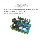
PSU-1848 Power Supply Kit

Circuit Operation:

RECT1 is a bridge rectifier for the 48V section that converts the input AC voltage to DC.  C1 and C2 is a filter capacitor that filters
the ripple voltage after the rectifier.

This filtered DC voltage then goes to IC1, which is a 3-terminal adjustable voltage regulator. The values for R1, R2 and R3 are
chosen so that you can achieve a +48V output. R3 is a trimmer resistor that is used for fine-tuning the output voltage.

D1 and D2 are diodes that protect the IC1 voltage regulator. C3 is added for stability, along with bypass capacitors C4 and C5.
C18 is another filter capacitor to further reduce ripple from the 48V section. Since the 48V output will be used for phantom
power, we want it to be as clean as possible to prevent the mic preamp from amplifying any ripple/hum in the supply.

RECT2 is another bridge rectifier for the split supply section.  C8, C9 are filter capacitors to smoothen out the ripple. C10 and
C11 are bypass capacitors, along with C12, C13, C14 and C15. IC2 is a positive 3 terminal voltage regulator while IC3 is it’s
counterpart negative 3 terminal voltage regulator.  D3, D4, D5, and D6 are protection diodes for the regulator.

Resistor values R4, R5 are chosen so IC2 and IC3 (along with resistors R6 and R7) will /-18Volts. R6 and R7 are trimmer
resistors used for adjusting the output voltage.

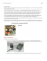
Resistors R8 and R9 are current limiting resistors for LED1 and LED2.  You can solder LEDs to the PCB as a visual reminder if the
board is powered up. Or, you can to mount your LEDs to your front panel as a visual indicator for the (+) and (-) supply voltage.

Basic Tools Required

A few basic tools are required to build this kit.

1.


Soldering iron – adjustable temperature recommended, but not necessary. Your soldering iron must have a sharp
conical tip.  I do not recommend a “flat-head, screwdriver-type” soldering iron. DO NOT USE A SOLDERING GUN. They
are usually rated at 100Watts and are overkill for this project.


2.


Mini Pliers Cutter – to cut component leads, wires, strip insulation off wires (if you don’t have a wire-stripper tool).

Содержание PSU-1848

Страница 1: ...ment may be reproduced either mechanically or electronically posted online on the Internet in whole or in part without the expressed written permission of FiveFish Studios This document is solely provided to the kit builder of the PSU 1848 2448 Power Supply Kit Copyright 2007 FiveFish Studios www fivefishstudios com Last Update 12 21 07 ...

Страница 2: ...orm factor measuring only 3 5 W x 1 9 H The PCB is professionally manufactured with double sided copper plated through holes and top silkscreen component labels This is designed to work with the SC 1 Mic Preamp Kit or any opamp preamp project Specs Regulated Voltages Output Range using PWR TRAFO kit transformer Output 1 20 Volts to 48 Volts Output 2 1 2 Volts to 21 Volts up to 25 Volts for PSU 244...

Страница 3: ...ormer please consult the manufacturer for their documentation 1U PWR TRAFO KIT 2U PWR TRAFO KIT USING THE 1U PWR TRAFO KIT TRANSFORMER photo shown above 110 VOLT OPERATION For 110V operation we need to connect the primaries in parallel Connect the BLUE and VIOLET wires together Connect the GRAY and BROWN wires together Connect both across the 110V line USING THE 2U PWR TRAFO KIT TRANSFORMER photo ...

Страница 4: ...ACK wires see diagram above For Both 110V or 220V OPERATION On the secondary side we need to connect the RED and ORANGE together this will be the center tap wire CT The center tap wire will connect to the CT pad on the PCB Connect the BLACK wire to AC1 on PSU PCB Connect the YELLOW wire to AC2 on PSU PCB For Both 110V or 220V OPERATION On the secondary side we need to connect the BLUE and GREEN wi...

Страница 5: ...n out the ripple C10 and C11 are bypass capacitors along with C12 C13 C14 and C15 IC2 is a positive 3 terminal voltage regulator while IC3 is it s counterpart negative 3 terminal voltage regulator D3 D4 D5 and D6 are protection diodes for the regulator Resistor values R4 R5 are chosen so IC2 and IC3 along with resistors R6 and R7 will supply 18Volts R6 and R7 are trimmer resistors used for adjusti...

Страница 6: ... 7 Magnifying glass to see what you re doing 8 Clean and well lighted work area Lots of good lighting clean work area You want to be able to leave your work in progress without packing everything away Extra Tools Nice to have but not required 1 Vacuum desoldering pump if you make a mistake you need to pull out the component from the PCB 2 Component lead bender bend component leads like resistors u...

Страница 7: ...these instructions to assemble your PSU 1848 Power Supply Bend the component leads like the photo shown below before inserting them to the PCB For diodes allot a small clearance before bending the leads Step 1 Solder all resistors and diodes to the PCB R1 R2 R4 R5 R8 R9 ...

Страница 8: ...Page 8 PSU 1848 Power Supply Kit White band of diode is oriented on top Step 2 Solder all ceramic capacitors to the PCB These are the small yellow components C2 C5 C10 C11 C12 C13 ...

Страница 9: ...mer resistors Step 7 Solder the medium sized capacitors C6 C7 Step 8 Solder capacitors C8 C9 Step 9 Solder capacitors C1 and C18 These are snap in type capacitors You may need to do a slight twising motion when inserting it into the holes Step 10 Solder voltage regulators IC1 IC2 IC3 For aesthetic reasons keep all their height at the same level The flat side i e metal side of the regulators should...

Страница 10: ...erminals We want a voltage reading of 48Volts if you re using this for the SC 1 Mic Preamp project You probably won t exactly get 48Volts so using a small screwdriver adjust leftmost trimmer R3 to measure 48 volts at the outputs Turn the screwhead COUNTERCLOCKWISE to increase the voltage 2 Next measure the voltage across and GND pads Adjust the middle trimmer R6 to get 18V at the outputs Turn the ...

Страница 11: ... be modified for a higher 24V max output useful if you re powering a Neve clone or some vintage gear that requires a higher voltage than 18V And of course 48V phantom power is still available The modifications are as follows R4 and R5 needs to be changed to 220 ohms R6 and R7 trimmer needs to be changed to 5Kohm ...

Страница 12: ...Page 12 PSU 1848 Power Supply Kit Photos Note the placement of the heatsinks You need a 4 40x1 4 screw and a 4 10 hex nut to install the heatsinks to the TO 220 regulators ...

Страница 13: ...r 24V output use 220R for R4 R5 R6 R7 2K TRIM Bourns top adjust trimmer For 24V output use 5K TRIM for R6 R7 C1 C18 1000uf 80V Electrolytic Snap in type C3 C16 C17 10u 63V Electrolytic C4 C14 C15 1u 63V Electrolytic C6 C7 100uf 100V Electrolytic C8 C9 1000uf 50V Electrolytic C2 C5 C10 C11 C12 C13 0 1u 100V ceramic H1 H2 H3 Heatsinks for TO 220 PCB PSU 1848 PCB www fivefish net diy PSU 1848 PCB Com...

Отзывы: