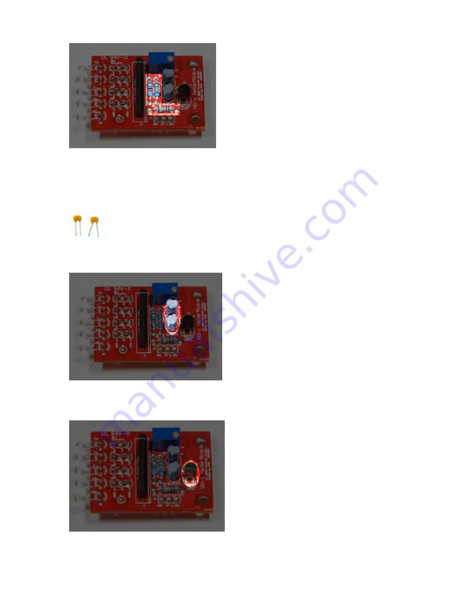
STEP 2. Solder all 1/4-watt resistors and inductors to the PCB. The orientation does not matter.
Build Notes: There are some discrepancies between the silkscreen on the PCB and parts list.
PCB value 6K32 = 6K34 on parts bag
PCB value 8K = 8K2 on parts bag
STEP 3. Solder the ceramic capacitor to the PCB. The orientation does not matter. The ceramic capacitor is
located just above the voltage regulator.
STEP 4. Solder the two electrolytic capacitors. Note orientation of (-) leg. The negative leads should be as
shown in the photo below:
Note: The (-) leads are oriented on top.
STEP 5: Solder the Voltage Regulator. Note the orientation of where the “flat side” is facing.


