7
ASSEMBLY INSTRUCTIONS
STEP 1 :
Front and Rear Stabilizers Installation
Attach the Front Stabilizer (6) onto the front curve of the Main Frame (1) with two M8x65 Bolts
(35), two Φ8xΦ20x1.5 Arc Washers (36) and two M8 Cap Nuts (34). Tighten cap nuts with the
Spanner with Phillips Screwdriver provided.
Attach the Rear Stabilizer (4) onto the rear curve of the Main Frame (1) with two M8x65 Bolts (35),
two Φ8xΦ20x1.5 Arc Washers (36) and two M8 Cap Nuts (34). Tighten cap nuts with the Spanner
with Phillips Screwdriver provided.
STEP 2 :
Left and Right Foot Pedals Installation
The Cranks, Pedal Shafts, and Foot Pedals are marked “R” for Right and “L” for Left.
Insert pedal shaft of Left Foot Pedal (20) into threaded hole in the left side of Crank. Turn the
pedal shaft by hand in counter-clockwise direction until snug.
Note: DO NOT turn the pedal shaft in the clockwise direction, doing so will strip the threads.
Tighten the pedal shaft of Left Foot Pedal (20) with the Spanner with Phillips Screwdriver
provided.
Insert pedal shaft of Right Foot Pedal (21) into threaded hole in the right side of Crank. Turn the
pedal shaft by hand in clockwise direction until snug. Tighten the pedal shaft of Right Foot Pedal
(21) with the Spanner with Phillips Screwdriver provided.
Содержание F4H-EB-KPR65910
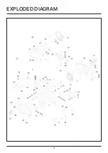
Страница 4: ...4 EXPLODED DIAGRAM...
Страница 10: ...10 ASSEMBLY INSTRUCTIONS STEP 5 Computer Installation...
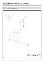
Страница 12: ...12 ASSEMBLY INSTRUCTIONS STEP 7 Seat Post Installation...
Страница 19: ...19...


