Fisher TW-82P Скачать руководство пользователя страница 13

13

LATERAL MODE continued
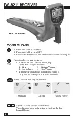
TW-82P RECEIVER


Press            to enter Lateral Mode.

will appear on the LCD display.

LATERAL TRACING OPERATION

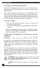
While tracing a line using the Lateral Mode, the display will appear as 

illustrated below.  The SIGNAL number indicates the strength of the 

field emitted by the buried line.  The buried line is located at the spot 

where the maximum SIGNAL number

is indicated. If you move left or right

of the spot where the maximum

SIGNAL number is found, the value

displayed will fall.

Walk across the location of 

the lateral line with the blade 

perpendicular to the lateral line.


Programming:

While in Lateral Mode, press-and-hold            to program:

• To exit Lateral programming,  press-and-hold           again.
• To set the upper limit of the signal range, press          .

Each press of           toggles through the program choices:

50, 100, 150, 200, 250 or 300

Set this upper limit just above the maximum SIGNAL strength 

number that appears during your lateral trace.
The correct setting will make it easier to hear the peak in the 

signal as you pass over the lateral line.

Set the number just above the highest SIGNAL number.

Examples:
If the highest lateral

SIGNAL number is: 

Set to:

137 

150

159 

200

310 

300 

(300 is the maximum possible)

Changes to this upper limit of the 

SIGNAL RANGE are saved to memory.

Changing this upper limit is similar 

to the gain adjustment on other line 

tracers which use a peak mode of 

operation.  Set the number just above 

the highest SIGNAL number, as 

described above.

Test Equipment Depot - 800.517.8431 - 99 Washington Street Melrose, MA 02176

 TestEquipmentDepot.com 

Содержание TW-82P

Страница 1: ...TW 82P Operating Manual DIGITAL LINE TRACER WITH PASSIVE POWER DETECTION Test Equipment Depot 800 517 8431 99 Washington Street Melrose MA 02176 TestEquipmentDepot com...

Страница 2: ...nductive Locating 7 Receiver 8 17 Control Panel 8 Standard Mode 9 11 Lateral Mode 12 14 Lateral Tracing Operation 13 Lateral Mode Programming 13 Passive Power Mode 14 16 Auto Power Down Receiver 17 Me...

Страница 3: ...location is required so that the Transmitter can be placed and oriented on the ground near the utility in the most effective manner 3 Coupling In some cases a utility may be exposed but does not provi...

Страница 4: ...4 CONTENTS Carrying Case Ground Rod Assembly Ground Rod Conductive Tracing Cables Receiver Transmitter 6 D cell Batteries Operator s Manual Calibration Certificate...

Страница 5: ...ng battery indicator followed by a blank screen or the illuminated battery indicator An illuminated battery indicator means Auto Power Down is activated A blank screen means Auto Power Down is deactiv...

Страница 6: ...put Jack 2 Connect the conductive tracing cable plug for conductive tracing When the conductive tracing cable is connected Signal Current will be displayed The Signal Current Bar Graph shows the quali...

Страница 7: ...lugged in the Signal Current display will illuminate CONDUCTIVE LOCATING 1 Place the Transmitter on the ground and turn it off 2 Connect the Conductive Tracing Cables to the Transmitter 3 Push the Gro...

Страница 8: ...ct volume settings In Standard and Lateral Modes tap the button to adjust volume 1 Mute 3 Medium Volume 2 Low Volume 4 High Volume In Passive Power Mode no mute is available Only volume settings 2 3 4...

Страница 9: ...h Battery Strength 1 Signal Strength Indicates your proximity to the center of the electromagnetic field emitted by the utility 999 maximum value 0 minimum value You may find different locations where...

Страница 10: ...NCE FROM UTILITY When you are standing to the right of the utility you will hear a constant tone and to the left a pulsating sound 3 Azimuth These rotational arrows indicate the utility s path relativ...

Страница 11: ...ld strength and the roundness of the field The only 100 reliable method for determining the depth of any buried utility is to hand excavate 6 Battery Strength When battery life declines to less than o...

Страница 12: ...lel to the main line as in the illustration below You must use Lateral Mode in this situation because in the Regular Mode you may detect the signal from the main line all of the way up to the house ev...

Страница 13: ...g press and hold again To set the upper limit of the signal range press Each press of toggles through the program choices 50 100 150 200 250 or 300 Set this upper limit just above the maximum SIGNAL s...

Страница 14: ...infrastructure and each specific area being located to interpret the character of each underground utility ABSENCE OF A DETECTABLE POWER SIGNAL DOES NOT GUARANTEE THAT NO POWER IS PRESENT Among the im...

Страница 15: ...play Azimuth depth and left right guidance will not be provided 6 When an audible signal indicates the detection of a utility a Move left and right sweeping beyond the range of the signal each time as...

Страница 16: ...re complete coverage of the area map out a grid of intersecting lines covering the search area Walk the grid at intersecting right angles Power lines will be detected when the blade of the Receiver is...

Страница 17: ...Power Down press any button once METRIC IMPERIAL UNIT OF MEASURE To change the Receiver unit of measure follow this procedure 1 Start with the Receiver OFF 2 Press and Hold for 6 seconds a The Receiv...

Страница 18: ...ty to specific use Fisher Research Laboratory shall in no event be liable for any direct incidental consequential or indirect damages Output Frequency 82 175 kHz Output Power nominal Normal Setting 0...

Страница 19: ...19 Test Equipment Depot 800 517 8431 99 Washington Street Melrose MA 02176 TestEquipmentDepot com...

Страница 20: ...the TW 82 35 x 7 x 16 Fisher Sonde Signal Transmitter 82kHz SONDE 82 175 Small transmitter used to trace the path of non metallic pipes and locate blockage in lines Sonde is inserted into a pipe or d...

Отзывы: