


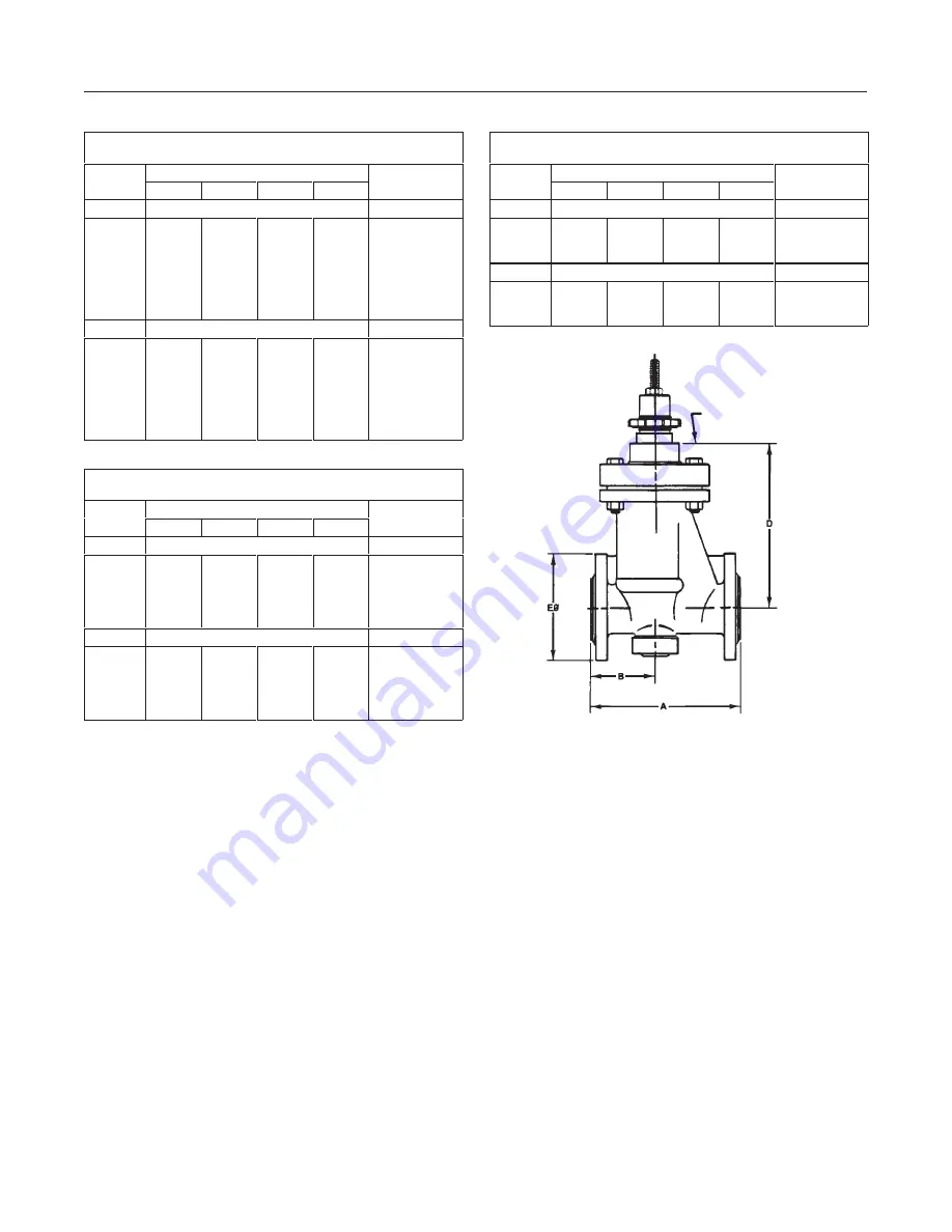
Figure 3. Dimensions and Weights
MATCH LINE
FOR ACTUATOR
10B4744–G
A5216-1 / IL
Design RSS
4
DIN FACE-TO-FACE DIMENSIONS
MATING WITH ANSI CLASS 150 FLANGES
Valve
Dimensions
Approximate
Valve
Size
A
B
D
E
O
Approximate
Weight
Inches
Inches
Pounds
1/2
3/4
1
1-1/2
2
3
4
5.12
5.12
6.30
7.88
9.06
12.20
13.78
2.36
2.36
2.83
3.38
3.82
5.04
6.94
5.57
5.57
7.83
8.66
8.98
13.00
13.39
3.50
3.86
4.53
5.91
6.50
7.87
8.66
13
13
23
38
43
86
92
Inches
mm
kg
1/2
3/4
1
1-1/2
2
3
4
130.0
130.0
160.0
200.0
230.0
310.0
350.0
60.0
60.0
72.0
86.0
97.0
128.0
176.0
141.5
141.5
199.0
220.0
228.0
330.0
340.0
89.0
98.0
115.0
150.0
165.0
200.0
220.0
6
6
11
17
20
39
42
ANSI/ISA CLASS 150 FACE-TO-FACE DIMENSIONS
MATING WITH ANSI CLASS 150 FLANGES
Valve
Dimensions
Approximate
Valve
Size
A
B
D
E
O
Approximate
Weight
Inches
Inches
Pounds
1
1-1/2
2
3
4
7.25
8.75
10.00
11.75
13.78
3.27
3.82
4.21
4.76
6.94
7.83
8.66
8.98
13.00
13.39
4.25
5.00
6.00
7.50
8.66
23
36
43
86
92
Inches
mm
kg
1
1-1/2
2
3
4
184.0
222.0
254.0
298.0
350.0
83.0
97.0
107.0
121.0
176.0
199.0
220.0
228.0
330.0
340.0
108.0
127.0
152.4
190.5
220.0
10
17
20
39
42
ANSI/ISA CLASS 300 FACE-TO-FACE DIMENSIONS
MATING WITH ANSI CLASS 300 FLANGES
Valve
Dimensions
Approximate
Valve
Size
A
B
D
E
O
Approximate
Weight
Inches
Inches
Pounds
1
1-1/2
2
7.75
9.25
10.50
3.54
3.97
4.53
7.83
8.66
8.98
4.87
6.14
6.50
25
40
45
Inches
mm
kg
1
1-1/2
2
197.0
235.0
267.0
90.0
101.0
115.0
199.0
220.0
228.0
123.8
156.0
165.0
11
18
20
1. Before installing the valve, inspect it to be certain
that the valve cavity is free of foreign material. Use
extra care in handling to avoid damage to the exposed
lining on the flanges. Clean out all pipelines to remove
scale, welding slag, and any other foreign materials
that could cause erosion of the valve body lining.
2. The control valve assembly should be installed in a
horizontal pipeline with the valve stem in a vertical
position. Before installing in any other orientation, con-
sult your Fisher Controls sales office or sales repre-
sentative.
Flow through the valve must be in the direction indi-
cated by the arrow cast on the valve (figure 7).
3. Use accepted piping practices when installing the
valve in the pipeline. For a 1/2-inch valve only, use the
line flange cap screws (key 18, not shown) provided
rather than using through bolting. To minimize valve
damage caused by expansion of PTFE lined pipe, use
a line flange gasket (figure 4). This gasket evenly dis-
tributes the piping loads across the valve flange face
and minimizes the potential for cutting or indenting the
lined face on the valve flange.
4. With a leak-off bonnet construction, remove the
pipe plug (key 20, not shown) and install the leak-off
piping into the tapping in the bonnet (key 2, figure 9).
5. If continuous operation is required during inspec-
tion or maintenance, install a three-way bypass around
the control valve assembly.
6. For a valve used with a fail-closed actuator, re-
move the shim (key 24, not shown) from between the
bonnet and the travel stop. Discard the shim.