


C1 Controllers and Transmitters
Instruction Manual
September 2009
27
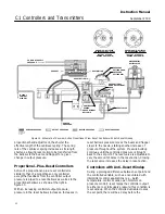
CONNECTING
LINK (KEY 16)
PROPERLY ALIGNED
CONNECTING LINK
BINDING CONNECTING LINK
(IMPROPERLY ALIGNED)
BEAM
(KEY 39)
WASHER
(KEY 62)
LINK BEARING
(KEY 31)
BOURDON TUBE
(KEY 5)
WASHER
(KEY 62)
BOURDON TUBE
(KEY 5)
LINK BEARING
(KEY 31)
WASHER (QTY 2)
(KEY 62)
BEAM
(KEY 39)
CONNECTING LINK
(KEY 16)
GE37119
Figure 17. Connecting Link
10. Replace the subassembly in the case and
secure with the four machine screws (key 41,
figure 21 or 22). Reconnect all tubing.
11. If a bellows assembly with a different range is
installed, remove the machine screw and washer
(keys 61 and 60) and dial (key 6), and install a new
dial having an adjustment range corresponding to
the range of the bellows. If an optional process
pressure gauge (key 4, figure 21) is being used,
install a new gauge with the appropriate
measurement capability.
12. Check all tubing connections for leaks and the
bellows yoke machine screws, tighten as necessary.
Perform the appropriate calibration procedures.
Changing Reset Valve
1. Disconnect the appropriate tubing and remove
the reset restriction valve assembly (key 256,
figure 22) by removing the screw (key 22, not
shown) from the back of the case. Install the desired
replacement assembly.
2. Connect the tubing, check all connections for
leaks and perform the appropriate calibration
procedures.
Changing Anti
−
Reset Windup
Differential Relief Valve
Refer to figure 23 for key number locations.
1. Note the controller output pressure (zero or
supply) when the process is shut down.
2. Remove the differential relief valve assembly.
3. Refer to figure 14. Install the replacement relief
valve with the arrow positioned so that the controller
output will be as noted in step 1 when the process is
shut down.
Changing Action
Proportional
−
Only to a Differential Gap
Controller
A proportional
−
only controller may be changed to a
differential gap controller, or vice versa, by changing
the position of the proportional tubing and inverting
the proportional band assembly.
1. Isolate the controller or transmitter from process,
control, and supply pressure. Vent any trapped
pressure from the controller or transmitter before
proceeding with the following steps.
2. Disconnect the proportional tubing (key 25,
figure 16) from the mounting base (key 57, figure 23
or 24) and reinstall it in the other connection in the
mounting base.
3. Do not invert the reversing block unless also
changing the controller action from direct to reverse
(or vice versa).
4. Invert the proportional band assembly (refer to
figure 18):
a. Turn the proportional band adjustment knob
(key 73) to 10.
b. Unscrew the spring adjustor (key 65),
removing the bias spring (key 70) and washers
(key 64) with it.


