Instruction Manual
D100714X012
461 Valve
June 2017
15
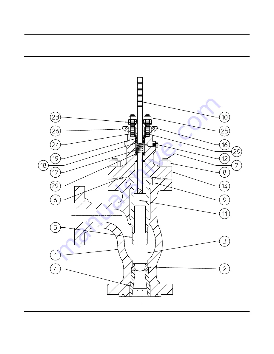
Figure 6. Fisher 461 Valve Assembly
KEYS 33, 34, 35, 36, 37, 40, 41, AND 42 NOT SHOWN
Страница 1: ...ion The 461 valve figure 1 is a self cleaning increased outlet angle valve that is typically used in the chemical and hydrocarbon industries where control of residual oils or other liquids with coking properties is necessary The 461 features a venturi type throat which is useful in power plants or slurry services where high pressure drops and flashing might exist Do not install operate or maintain...
Страница 2: ...es for Fisher 461 valves as well as a variety of other products contact Emerson Automation Solutions Educational Services Registration Phone 1 641 754 3771 or 1 800 338 8158 E mail education emerson com emerson com fishervalvetraining Installation WARNING To avoid personal injury or equipment damage caused by sudden release of pressure install the valve assembly only where service conditions will ...
Страница 3: ...t to ENVIRO SEAL packing refer to the retrofit kits listed in the parts kit sub section near the end of this manual Maintenance Valve parts are subject to normal wear and must be inspected and replaced as necessary The frequency of inspection and replacement depends upon the severity of service conditions WARNING Avoid personal injury or property damage from sudden release of process pressure or b...
Страница 4: ...s with temperatures over 260_C 500_F WARNING Do not lubricate parts when used in oxygen service or where the lubrication is incompatible with the process media Any use of lubricant can lead to the sudden explosion of media due to the oil oxygen mixture causing personal injury or property damage If a lubricator or lubricator isolating valve figure 2 is provided for PTFE composition or other packing...
Страница 5: ...procedure are shown in figure 6 unless otherwise indicated When using packing with a lantern ring it may be possible to add packing rings above the lantern ring as a temporary measure without removing the actuator from the valve body 1 Isolate the control valve from the line pressure release pressure from both sides of the valve body and drain the process media from both sides of the valve If usin...
Страница 6: ... 39 PACKING FOLLOWER KEY 29 PACKING BOX RING KEY 38 LANTERN RING KEY 30 GRAPHITE FILAMENT PACKING RING KEY 20 GRAPHITE RIBBON PACKING RING KEY 20 1 2 12A8160 A 14A3412 C PTFE V RING SINGLE PACKING GRAPHITE RIBBON AND FILAMENT SINGLE PACKING KEY 22 UPPER WIPER KEY 16 PACKING FOLLOWER KEY 29 FEMALE ADAPTOR KEY 22 V RING KEY 19 MALE ADAPTOR KEY 21 LANTERN RING KEY 30 PACKING BOX RING KEY 38 LOWER WIP...
Страница 7: ... W5803 3 SPRINGS ANTI EXTRUSION RING LANTERN RING PACKING BOX STUDS PACKING RING VALVE BONNET TYPICAL ENVIRO SEAL PACKING SYSTEM WITH PTFE PACKING TYPICAL ENVIRO SEAL PACKING SYSTEM WITH GRAPHITE ULF PACKING TYPICAL HIGH SEAL PACKING SYSTEM WITH GRAPHITE ULF PACKING TYPICAL ENVIRO SEAL PACKING SYSTEM WITH DUPLEX PACKING 1 FOR A FLAT BOTTOM PACKING BOX THE PACKING BOX RING AND LOWER WIPER ARE NOT N...
Страница 8: ...oximately 3 mm 1 8 inch Then loosen the body to bonnet gasketed joint by either rocking the bonnet or prying between the bonnet and valve body Work the prying tool around the bonnet until the bonnet loosens If no fluid leaks from the joint proceed to the next step 6 Unscrew the hex nuts key 8 and carefully lift the bonnet off the valve stem If the valve plug and stem assembly starts to lift with t...
Страница 9: ...e body Then slide the bonnet over the stem and onto the studs key 7 Note The prelubricated hex nuts key 8 referred to in step 14 can be identified by a black film coating on the nut threads The proper bolting procedures in step 14 include but are not limited to ensuring that the bonnet stud threads are clean and that the hex nuts are evenly tightened to the specified torque values CAUTION Failure ...
Страница 10: ...ey 25 Replace the packing flange nuts For the spring loaded PTFE V ring packing shown in figure 3 tighten the packing flange nuts until the shoulder on the packing follower key 29 contacts the bonnet For graphite packing tighten the packing flange nuts to the maximum recommended torque shown in table 2 Then loosen the packing flange nuts and retighten them to the recommended minimum torque shown i...
Страница 11: ...for PTFE Type Packing Flange Nuts non live loaded VALVE STEM DIAMETER PRESSURE RATING TORQUE NSm lbfSft mm Inches Min Max Min Max 19 1 3 4 CL600 10 15 7 11 CL900 27 41 20 30 CL1500 34 50 25 37 CL2500 41 61 30 45 25 4 1 CL600 17 25 13 18 CL900 42 62 31 46 CL1500 52 77 38 57 CL2500 61 91 45 67 31 8 1 1 4 CL600 24 36 18 27 CL900 56 83 41 61 CL1500 68 102 50 75 CL2500 81 122 60 90 4 With the stem and ...
Страница 12: ...there is no gasket between the seat ring and the valve body make sure that the mating surfaces are clean and free of nicks and scratches 2 Replace the liner key 5 Then slide the valve plug and stem assembly keys 3 and 10 into the valve body key 1 3 Mount the bonnet key 14 onto the valve body key 1 being careful not to damage the gasket Note If the seating surfaces of the valve plug and seat ring r...
Страница 13: ...he leakage becomes excessive however the condition of the seating surfaces of the valve plug and seat ring can be improved by grinding Large nicks should be machined out rather than ground out Use a commercial lapping compound or a mixture of 600 grit Carborundum and solidified vegetable oil Apply the compound to the bottom of the valve plug and apply white lead to the seat ring to prevent excessi...
Страница 14: ...Contact your Emerson sales office or Local Business Partner for Part Ordering information Key Description 1 Valve Body If you need a valve body as a replacement part order by valve size serial number and desired material 2 Seat Ring 3 Valve Plug 4 Seat Ring Retainer 5 Liner 6 Gasket N04400 7 Stud Bolt 8 req d for NPS 2x3 through NPS 4x6 12 req d for NPS 6x8 8 Hex Nut 12 req d for NPS 6x8 8 req d f...
Страница 15: ...Instruction Manual D100714X012 461 Valve June 2017 15 Figure 6 Fisher 461 Valve Assembly KEYS 33 34 35 36 37 40 41 AND 42 NOT SHOWN ...
Страница 16: ...rein or their use or applicability All sales are governed by our terms and conditions which are available upon request We reserve the right to modify or improve the designs or specifications of such products at any time without notice E 1981 2017 Fisher Controls International LLC All rights reserved Fisher and ENVIRO SEAL are marks owned by one of the companies in the Emerson Automation Solutions ...