Fisher & Paykel OR90SDBSIPX1 Скачать руководство пользователя страница 7

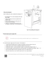
Fixing the backguard

Before installing the cooker, assemble the backguard “C”
.

• The backguard “C” can be found packed at the rear

of the cooker.

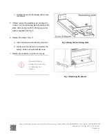
1. Before assembling, remove any protective film/

adhesive tape.

2. Remove the two spacers “A” and the screw “B”

from the rear of the cooktop.

3. Assemble the backguard as shown and fix it by

screwing the central screw “B” and the spacers “A”.

Fig. 11 Assembling the backguard

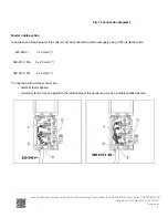
Connecting the power supply cable

This cooker must be connected to the electricity supply only by an authorised person.

To connect the power supply cable to the cooker, it is necessary to:

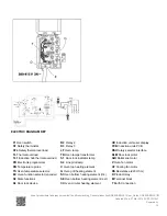
1. Unhook the terminal board cover by inserting a screwdriver into the two hooks ‘A’ (fig. 12).

2. Unscrew the screw ‘D’ and open completely the cable clamp ‘E’ (figs. 14).

3. Position the U bolts ‘F’ onto terminal board ‘G’ (figs. 14) according to the diagrams in fig. 13.

4. Connect the phase, neutral and earth wires to terminal board ‘G’ according to the diagrams in figs. 13 - 14.

5. Strain the feeder cable and block it with cable clamp ‘E’ (by screwing screw ‘D’).

6. Close the terminal block cover (check the two hooks ‘A’ are correctly hooked).

https://producthelp.fisherpaykel.com/nz/Cook/Freestanding_Cookers/Induction/OR90SDBSIPX1/User_Guide_OR90SDBSIPX1/02_Installation_instructions

Updated: Wed, 27 Mar 2019 03:09:12 GMT

Powered by

7

Содержание OR90SDBSIPX1

Страница 1: ...urrounding the cooker must be made of heat resistant material and must be able to withstand temperatures of 65 C above room temperature Do not install the cooker near flammable materials eg curtains I...

Страница 2: ...1 Area for electrical connection Fig 2 Dimensions and distances from cooker https producthelp fisherpaykel com nz Cook Freestanding_Cookers Induction OR90SDBSIPX1 User_Guide_OR90SDBSIPX1 02_Install Up...

Страница 3: ...ve the kickstrip unscrew the two screws holding it in place The cooker is already fitted with four levelling feet Level the cooker by screwing or unscrewing the feet Make sure you follow the instructi...

Страница 4: ...or electrical wires 2 Attach the anti tilt bracket to the floor and rear wall using the four screws supplied as shown in Fig 4 3 After attaching the anti tilt bracket securely slide the cooker into pl...

Страница 5: ...rt the drawer rails into the guide rails b Gently push the drawer in completely the safety catches will automatically hook 7 Replace the kickstrip using the two screws Beware of sharp edges when remov...

Страница 6: ...oker Lift the feet clear of the floor Take extra care not to damage the door sensor top left of oven Fig 8 Correctly lifting the cooker Fig 9 Incorrectly lifting the cooker Fig 10 Incorrectly moving t...

Страница 7: ...power supply cable to the cooker it is necessary to 1 Unhook the terminal board cover by inserting a screwdriver into the two hooks A fig 12 2 Unscrew the screw D and open completely the cable clamp...

Страница 8: ...replaced only by an authorised service agent in order to avoid a hazard Voltage and power consumption 220 240 380 415 V 3N 50 Hz 47 2A 230V 10850 W diversity not applied Fig 12 Terminal block https p...

Страница 9: ...V 3N 5 x 2 5 mm2 380 415 V 2N 4 x 6 mm2 Connection with wall box connection Diversity factor applied A diversity factor may be applied to the total loading of the appliance only by a suitably qualifi...

Страница 10: ...e pilot lamp C Oven top heating element G Oven grill heating element SI Oven bottom heating element int SE Oven bottom heating element ext CI Oven circular heating element UD Induction units user disp...

Страница 11: ...Induction unit left zones IU RH Induction unit right zones https producthelp fisherpaykel com nz Cook Freestanding_Cookers Induction OR90SDBSIPX1 User_Guide_OR90SDBSIPX1 02_Install Updated Wed 27 Mar...

Отзывы: