


DIAGNOSTIC MODE GW
Data Display
To enter the
Data Display
screens, push the
Lifecycles
button again. One
of three displays will appear in the screen (detailed below). To scroll
through the different screens use the
Options Up
or
Down
buttons.
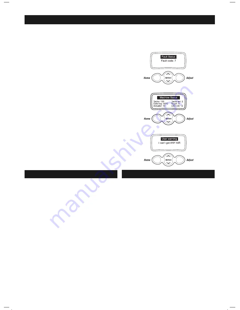
Fault Status Screen
This screen will indicate the last fault code that occurred. If a fault is
registered the fault code is saved to EEPROM, which retains its memory
even when the power is switched off. The fault code will remain visible
until another fault code overwrites it.
Machine Status Screen
Tacho:
This displays the position of the drum. The displayed
fi gure is updated every fi ve seconds and will change as
the drum revolves.
Exht tmp:
This displays the temperature in ºC of the exhaust sensor.
Actuator:
This displays the current draw in milli-amps of the
actuator motor.
Tacho Err:
During reversals of the drum there will often be a transient
error because of uncertainty of direction during the
reversing process, but this should be connected to the next
revolution.
Touch:
This displays the impendance of the conductivity contacts.
LED Cnt:
This is a measure of the infra-red light intensity required
to sense the drum position. It is normally about 14 but can
range from 5 to 53.
Warning Status Screen
The last User Warning will be displayed on this screen and will be
displayed until another User Warning overwrites it.
Entering the Diagnostic Mode
To enter the
Diagnostic Mode
press and hold the
Lifecycles
button and then the
Power
button. The machine will give 2 short beeps and the LCD screen
will go blank. Make sure that the buttons are released after the beeps.
Note: Provided the power supply to the machine is switched on, diagnostic mode may be entered at any time.
DIAGNOSTIC MODE I (INTUITIVE)
DISASSEMBLY
TESTING THE CONDUCTIVITY CONTACTS G & I
Impedance Testing G
To enter the conductivity impendance check, enter the diagnostic mode
then press the
Auto Dry
up button fi ve times. In this mode, touching damp
clothes or fi ngers across the conductivity contacts will cause the LED
display to change. If the contacts, or the harness to them, have gone open
circuit, no change will occur in the LED display. This is a useful method
of checking the integrity of the sensor cells.
To exit the diagnostic mode, press any cycle.
Impedance Testing I
It is possible to check the integrity of the conductivity contacts through
diagnostics. Firstly enter the Machine Status Screen, and when in this
mode, by touching damp clothes or fi ngers across the conductivity
contacts, the value adjacent to the word
Touch
will increase. The minimum
value is zero, this indicates an open circuit. The maximum value is 255.
No change in this value when touching the contacts, or conversely a
high value when not touching the contacts, would indicate a fault in this
circuit.
Resistance Testing (G and I)
An alternative, but slightly less reliable method of testing the conductivity
contacts, is to test the circuit with a multimeter. When using this method
to power to the dryer must be switched off. Place one probe of the
multimeter on each conductivity contact. The resistance should be
6.4 M
Ω
± 2%.
WARNING
Always disconnect the mains power supply before commencing service
work or disassembly of the dryer.
Pressing the Power button to turn the dryer off does not disconnect the
dryer from the power supply, even though the lights on the dryer control
panel are out.
Removing Lid
1. Open the lid to the upright position and lift it clear.
Removing Console
1. Remove the lid.
2. Remove 2 screws from the rear of the console. The console can be tilted
forward to gain access to the Display Module.
NOTE: Modules removed from the machine for return must be protected
from electrostatic damage while in transit by using the special package
in which the spare parts were received.
Removing Top Deck
1. Follow instructions for removal of console.
2. Remove 2 lid buffers from front side top of deck by levering upwards.
3. Remove 2 screws under buffers securing top deck to cabinet.
4. Tilt top deck upwards towards the rear
5. Disconnect display harness from sensor module, unclip and lift off Top
Deck.
Removing Front Panel
1. Unfasten & tilt back the Top Deck (Steps 1- 4 of Removing Top Deck).
2. Remove two screws from top (corners) of cabinet front.
3. Unclip cabinet front at sides, pull cabinet front forward, disconnect the
earth wire at the bottom of the cabinet front from the base panel and lift
the cabinet front clear.
3062 Smartload Summary UD.indd Sec1:3
3062 Smartload Summary UD.indd Sec1:3
12/8/05 11:42:28 AM
12/8/05 11:42:28 AM


