background image

CM6000


Install Guide

Alarm and Starter System

www.firstechonline.com | www.compustar.com

Copyright 2009 Firstech, LLC.

Page 30

At the end of menu 4, if diesel mode or auxiliary setting functions were enabled – or if any of the auxiliary out

-

puts were set to “Program”, the duration of these settings can now be adjusted.

Following the auxiliary and diesel settings (if selected), the POC options will be displayed on the OP500.  The 
POCs can be set between 0 (default) and 19.
 

STEP 3:

 When finished with the adjustment of the various option settings, press and hold the “W” (write) but

-

ton until the OP500 chirps, which is approximately 2.5 seconds. This will write the settings to the control mod-
ule. Wait until the module displays “Success” before disconnecting it from the antenna cable.

To reset the options, hold the “R” (reset) button and the “W” (write) button for 2.5 seconds. Release then write 
the reset, hold the “W” button until the OP500 chirps, which is approximately 2.5 seconds.  

Option Programming Using a Remote

Using a remote is a timed process so read this section in its entirety before beginning. 

IMPORTANT:

  Special 

Option Groups cannot be programmed with a remote – the OP500 must be used.

STEP 1:

 Select the option menu that contains the desired programming option. 

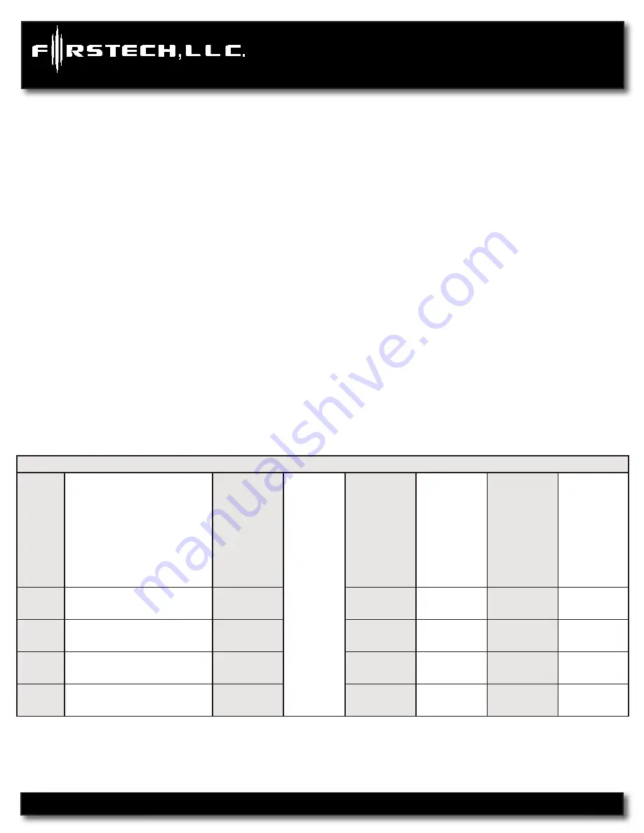
To program options use the following button combinations:

How to Program Options with 2-Way Remotes


W

ith 2 

W

ay 

Remotes 

(W

ait for

 chirp 

between each tap)

Scr

oll 

Thr

ough 

Menu 

(W

ait for

 chirp 

between each tap)

W

ait for

 corr

esponding parking light flash 

and/or

 sir

en chirp befor

e selecting the 

option

Select Option 1

Select Option 2

Select Option 3

Select Option 4

Option 

Menu 1

(1 + 2) for 2.5 seconds then 

(1 + 2) for 2.5 seconds

Tap Button 

4

Tap Button 

1

Tap Button 

2

Tap Button 

3

Tap Button 

4

Option 

Menu 2

(1 + 2) for 2.5 seconds then 

(1 + 4) for 2.5 seconds

Tap Button 

4

Tap Button 

1

Tap Button 

2

Tap Button 

3

Tap Button 

4

Option 

Menu 3

(1 + 4) for 2.5 seconds then 

(1 + 2) for 2.5 seconds

Tap Button 

4

Tap Button 

1

Tap Button 

2

Tap Button 

3

Tap Button 

4

Option 

Menu 4

(1 + 4) for 2.5 seconds then 

(1 + 4) for 2.5 seconds

Tap Button 

4

Tap Button 

1

Tap Button 

2

Tap Button 

3

Tap Button 

4

Содержание CM6000

Страница 1: ...sit www firstechonline com for additional installation resources MODEL RF 2W900FM 5PT Firstech LLC 21911 68th Ave S Kent WA 98032 Phone 888 820 3690 Fax 206 957 3330 Installation Manual CM6000 Alarm and Starter ...

Страница 2: ...Kit Contents 4 Installation Basics 5 Remote Programming Routine 6 Placement and Use of Components 7 Placement and Use of Components 8 Common Procedures 8 Wiring Descriptions 12 Option Programming Tables 19 Option Menu Descriptions 22 Special Option Groups 1 2 29 Option Programming 29 Troubleshooting 32 Frequently Asked Questions 32 Technical Support Contacts 35 ...

Страница 3: ...CM6000 Install Guide Alarm and Starter System www firstechonline com www compustar com Copyright 2009 Firstech LLC Page 3 ...

Страница 4: ...may change frequently Please check www firstechonline com for updates Kit Contents CM6000 All Firstech FT 6000AS CONT controllers include the following CM6000 main control module Wiring diagram sheet Main ignition wiring harness with two external relays Wiring harnesses Hood pin Mountable bright blue LED Firstech dual stage shock sensor RF Kits with remote s Antenna and Antenna Cable are not inclu...

Страница 5: ...t the units come in MANUAL transmission mode You will need to cut the green loop inside the con trol module if you are installing the unit in a AUTOMATIC transmission Tach learning procedure Learn tach by 1 Starting the vehicle with the key 2 Press and hold the foot brake then 3 Hold the re mote start button on the remote for 2 5 seconds one chirp and parking light flash indicates that the vehicle...

Страница 6: ...arking lights will flash once con firming each additional remote All systems except the PWSSR Pro can recognize up to three remotes Note If you do not program any remotes and enter this sequence it will put the system into Valet Mode Only the keyless entry will work in Valet Mode To exit Valet Mode just program remote s 2WSSR Pro STEP 1 Remove the AA battery from the remote STEP 2 Activate program...

Страница 7: ... example to enter 3 knock on the sensor 3 times each time you knock the LED will flash RED then wait STEP 5 The LED on the RPS will confirm your first number by flashing BLUE slowly Once the LED begins to flash rapidly in BLUE enter your second number by repeating step 4 STEP 6 Repeat steps 4 5 to enter all four numbers STEP 7 Turn the ignition OFF The RPS disarm unlock feature is now programmed R...

Страница 8: ... will still work Hood Pin The hood pin switch triggers the alarm in the event the hood is opened while the alarm is armed The hood pin also doubles as an important safety feature that prevents the remote start from engaging while the hood is open Backup Battery The backup battery input on the control module brain is for any optional battery backup unit sold separately The red positive lead acts bo...

Страница 9: ...d Key Start buttons for 2 5 seconds then tap the Trunk button for Aux 1 or the Key Start button for Aux 2 STEP 5 If you need to change the time settings of the outputs go to AU1 or AU2 on the OP500 LCD Line 2 is the timed output STEP 6 Hold the W Write button for 3 seconds to set all the options Tach Sensing The default engine sensing mode is tach In cold weather climates we recommend using an inj...

Страница 10: ...ther programming required other than adjusting crank time when necessary see below Adjusting Crank Time To adjust minimum crank times refer to Option 2 12 To help ensure successful starting the system will automatically add additional crank time to the 2nd and 3rd start attempts In addition there is a built in Smart Resting Mode Traditional tach sensing is still highly recommended for colder clima...

Страница 11: ...es not remain running check the emergency parking brake connection STEP 3 Exit the vehicle and close the door The vehicle s engine should shut off upon closing the door If the vehicle s engine does not shut off check the door trigger connection or wait for the factory dome light to go out The Firstech system is in reservation mode and the vehicle is ready to safely remote start Additional Notes Re...

Страница 12: ...trol module firmware NOTE The ADS RNG C1 ADS RNG C2 and ADS RNG GM3 are not included and must be purchased sepa rately The 20 pin Blade connector comes only with the Blade cartridge and not the CM6 control modules WARNING Manufacturer or seller assumes no responsibility for any injuries and or damages caused by improper care of the product such as decomposition conversion and transform done by a u...

Страница 13: ...oper wire will test 0V with the key in the off position 12V while the key is in the on posi tion and 12V during crank This pin also has a thin green wire that is prewired to the starter kill relay If you are not installing anti grind starter kill you do not need to con nect the thin 24 guage green wire Pin 4 Black Ground negative input This wire must be connected to the vehicle s ground Pin 5 Red ...

Страница 14: ... in the on position Pin 4 Light Blue Parking Emergency brake negative input This input is required for manual transmis sion reservation and turbo timer mode The proper wire will provide a trigger when parking emer gency brake is set Pin 5 Red Black POC 2 2nd Starter 250mA negative output This output can be used to trigger the pre wired relay located on the main ignition harness Pin 6 Light Blue Wh...

Страница 15: ...ug positive or negative input The proper vehicle wire will show a or trigger while the wait to start light is on This wire will delay the starter output momentarily to allow the glow plugs to warm up on vehicles equipped with a diesel engine You can adjust the delay with Option 2 3 Optional Key sense positive or negative input The proper wire will show a or trigger only when the key is in the igni...

Страница 16: ...comes with the Blade cartridge Please refer to the Blade install guide for wire description The new CM6 Series the Blade connector has a locking tab Non locking tab blade harnesses will work but you MUST TAKE CARE TO NOT PLUG THE HARNESS IN UPSIDE DOWN Make sure the two notches on the top of the harness face the top CM and barcode sticker side of the brain When looking at the wire side of the harn...

Страница 17: ...to this connector to monitor the vehicle s temperature It used in conjunction with Timer Start features along with displaying temperature on two way LCD s To use Timer Start features review Option Group 2 IMPORTANT Thermister plugs are blue 2 pin connectors on the CM6 series but old white plug Thermisters will still work Pin 1 Black Thermister Pin 2 Black White Thermister Connector 9 CN9 4 Pin to ...

Страница 18: ...e TX output This wire transmits the signal to remote Pin 3 Red Constant 12V positive output Pin 4 Black Negative ground Connector 11 CN11 2 Pin Pre wired LED Note Do not mistake for Thermister port Pin 1 Black L E D negative ground Pin 2 Black White L E D 3V positive output Connector 12 CN12 4 Pin Pre wired RPS Pin 1 Black Negative ground Pin 2 White Negative paging input Pin 3 Red 12V positive ou...

Страница 19: ...utput After Start Shutdown and First Lock After Start Shutdown and Every Lock After Start Only After Shutdown Only 1 06 Reservation Lock Manual transmissions Locks When Reserva tion Mode is Set Does Not Lock When Reservation is Set Reservation Sets 10 Seconds After the Last Door is Closed 1 07 Unlock Disarm With Trunk Release Unlock Factory Dis arm and Trunk Release Factory Disarm Trunk Release On...

Страница 20: ...n 2 08 Temperature of Cold Starting 10 C 14 F 20 C 4 F 5 C 23 F 15 C 5 F 2 09 Temperature of Hot Starting 25 C 77 F 30 C 86 F 35 C 95 F 40 C 104 F 2 10 Engine Sensing Tach Alternator No Connection No Tach Sensing Tachless Mode Only No Connection 1 5 Second Crank Not for Manual Trans missions 2 11 Turbo Remote Start Runtime Extension w 1 for 2 seconds No Yes 2 12 Crank Time Standard 0 2 Seconds to ...

Страница 21: ... Remote Start Shuts Down 3 15 Soft Disarm Off On Option Group 4 Feature Default Setting I Optional Setting II Optional Setting III Optional Setting IV 4 01 Aux 1 output 0 5sec Latch 20 sec Program 4 02 Aux 2 output 0 5sec Latch 60 sec Program 4 03 Aux 1 output Control By Remote Arm Disarm Negative out w ign shutdown 4 04 Aux 2 output Control By Remote Arm Disarm Panic 4 05 Secure Aux Output 1 and ...

Страница 22: ... Black 5 POC 5 Status GWR Black 6 POC 6 Rearm Wire Orange 7 POC 7 Disarm Wire Orange White 8 POC 8 Horn White 9 POC 9 Auxiliary 1 Violet Option Menu Descriptions CM6000 1 01 Unlock Before Lock After Starting Lock After Remote Start If enabled this option will make the system unlock the doors before remote starting start the vehicle then lock the doors after the vehicle starts It will then lock the...

Страница 23: ...ssed and doors closed Tach sensing mode must be used for setting 3 You must also turn this feature on through the remote by tapping I IV 2 Way remotes or Lock Key 1 Way remotes 1 10 Auto Relock This option will automatically relock rearm after the system has been disarmed and the doors have not been opened 1 11 Ignition Accessory Upon Unlock This option will pulse the ignition wire accessory or bo...

Страница 24: ...n dictates the time interval when the control mod ule will either remote start or check the temperature and remote start Default 1 Will start every 3 hours until the vehicle is remote started or started by key and run for 4 min utes Option 2 Will start every 1 5 hours until the vehicle is remote started or started by key and run for 4 minutes Option 3 Will start at the time specified on the 2 way ...

Страница 25: ...ult 1 Off Option 2 Factory Rearm This system will pulse the dome light output during lock arm Option 3 45 second Dome Light Output activates the dome light for 45 seconds upon unlock disarm Option 4 This is a combination of 2 and 3 3 03 Dome Light Delay This option is used when connecting the door trigger input to the vehicles dome light circuit It delays the door trigger input to prevent the door...

Страница 26: ...iary settings adds five additional independent auxiliary outputs for a total of seven With this op tion turned on auxiliary 2 becomes non functional and Aux 1 becomes the data wire for the Auxiliary settings Special Option Group 1 allows for independent timing of these outputs 3 12 Passive Arming w Auxiliary settings The ability to activate deactivate Passive Arming through the remote is lost once...

Страница 27: ...triggering of the outputs Option setting II turns this feature off 4 06 Aux 1 Input This option changes the input behavior of the pre warn wire on the Aux Input Sensor green connector Default 1 Will pre warn with a negative ground input Option 2 Will instant trigger with a negative ground input Option 3 Will disarm the alarm with a negative ground input Used when adding an alarm to a factory keyle...

Страница 28: ...232 Port Default setting allows for compatibility with ADS Idatalink modules Setting 2 changes compatibility to Fortin bypass modules 4 13 Antenna Power Save Some people may not drive their vehicle very often this may cause the battery to become discharged because it is not getting recharged on a regular basis The antenna power save option will turn off the antenna after the specified amount of ti...

Страница 29: ...cific output durations to be set for Aux 3 7 Only available with 2 Way LCD remotes Special Option Group 2 This special option group allows you to determine the output type of the POC wire For example if you want to set POC 5 default setting status out to Aux 1 you will need change special option 5 to number 10 This must be done with the OP500 Option Programming CM6000 Option Programming Using the ...

Страница 30: ...econds Option Programming Using a Remote Using a remote is a timed process so read this section in its entirety before beginning IMPORTANT Special Option Groups cannot be programmed with a remote the OP500 must be used STEP 1 Select the option menu that contains the desired programming option To program options use the following button combinations How to Program Options with 2 Way Remotes With 2 ...

Страница 31: ...for 2 5 seconds Tap Lock Button Tap Unlock Button Tap Key Start Button Hold Trunk Key Start for 2 5 seconds Option Menu 4 Lock Key Start for 2 5 seconds then Lock Key Start for 2 5 seconds Hold Trunk Key Start for 2 5 seconds Tap Lock Button Tap Unlock Button Tap Key Start Button Hold Trunk Key Start for 2 5 seconds STEP 2 Scroll through menu allowing for 1 parking light flash and or siren chirp p...

Страница 32: ...ansmission only 8 Tach or no tach sensing failure Pro 2 Way remotes will display the error number Strt Er on the LCD Alarm LED Diagnostics When the alarm is triggered the LED on the RPS if installed Secure Valet if installed and the LED if in stalled will flash a certain amount of times as shown in the table below This is intended for users with 1 Way remotes Priority Trigger LED Flash Diagnostic ...

Страница 33: ...med wire does the control module have one A You can use the starter output on CN1 that goes to the starter kill relay You must cut this wire and place a diode in line so that when the ignition on the other side of the relay goes to ground it won t back feed to your accessory Install the stripe side of the diode facing the control module Does the CM6 series have tachless mode A Yes The CM6000 and C...

Страница 34: ...Firmware Version Diagnostics A When you turn the Ignition on and hold buttons 1 and 4 or Lock and Key Start for 2 5 seconds then the park ing lights will flash 1 time on the CM6 series showing V 1 What is this cartridge slot on the rear of the CM6000 and CM6200 A This is the slot for the Blade cartridge system This slot is for the Idatalink Blade remote start bypass modules For more information on...

Страница 35: ...s only Monday Friday 888 820 3690 8 00 am 5 00 pm Pacific Coast Time Email support compustar com Web Register at www firstechonline com click on Authorized Tech Wire Diagrams Click on the Installogy Access Client link found on your desktop If you are a qualified dealer and unable to access this site call your sales representative or the number above Technical Support Contacts CM6000 ...

Отзывы: