Firich Enterprise RichPOS-2000 Скачать руководство пользователя страница 39

FIR-ULV600-DVR Main Board


33


12. 

Click 

Advanced


13. 

Click 

Intel(R) Extreme Graphics

Содержание RichPOS-2000

Страница 1: ...U Us se er r s s M Ma an nu ua al l RichPOS 2000 with FIR ULV600 1G DVR main board 8 4 14 1 inch LCD s...

Страница 2: ...o correct the interference by one or more of the following measures Reorient or relocate the receiving antenna Increase the separation between the equipment and the receiver Connect the equipment to a...

Страница 3: ...d must be rated for the product and for the voltage and current marked on the product s electrical ratings label The voltage and current rating of the cord should be greater than the voltage and curre...

Страница 4: ...ains information protected by copyright No part of this manual may be photocopied or reproduced in any form without prior written consent from the manufacturer 2005 All rights reserved The software de...

Страница 5: ...on 14 8 4 2nd TFT LCD Display Installation 16 VFD Customer Display Installation 19 MCR Parameter Modification 22 Cash Drawer Installation 23 CMOS Setup 23 C Ch ha ap pt te er r 3 3 2 24 4 Software Set...

Страница 6: ...g Systems Optional 57 C Ch ha ap pt te er r 4 4 5 58 8 Specifications 58 RichPOS 2000 W O Capture card Specifications 58 RichPOS 2000 W Capture card Specifications 60 MainBoard Configuration 62 I O bo...

Страница 7: ...tup RichPOS 2000 can be adapted for a variety of uses with the addition of any of the following options Capture Card Magnetic Card Reader VFD LCD customer display and Cash drawer Hard disk Modem LAN A...

Страница 8: ...als that you may have added Chapter 1 Provides an introduction to RichPOS 2000 and this manual Chapter 2 Provides all necessary information for all hardware setup Chapter 3 Provides the necessary info...

Страница 9: ...e you start take a few moments to become familiar with RichPOS 2000 RichPOS 2000 Keyboard Connector Board 9000CB0830 HDD Case HDD Internal I O Connector Board 9000CB0810 Front I O Door Aluminum Base F...

Страница 10: ...ront Cover LCD Panel Panel Holder IC Card Reader Connector Board Aluminum Back Cover MCR Connector Board Touch Panel Inverter LVDS Converter Board OSD Keypad Blanking Covers Hinge Holder Panel Holder...

Страница 11: ...FIR ULV600 DVR Main Board 5 Single LCD Panel Holder Dual LCD Panel Holder Hinge Cover LCD Mounting Post Cable Cover Secondary LCD Mounting Post...

Страница 12: ...display The following items are standard with RichPOS 2000 Main system with 14 or 8 LCD panel Power adapter User s guide FIR ULV600 DVR motherboard user s guide Motherboard chipset driver CD AC power...

Страница 13: ...FIR ULV600 DVR Main Board 7 RichPOS 200 Dimensions...

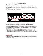
Страница 14: ...FIR ULV600 DVR Main Board 8...

Страница 15: ...e are USB version 2 0 ports and can be used to connect most USB devices VGA VGA Connector The VGA port is for use with an external LCD or CRT monitor K B PS 2 Keyboard Connector The K B port for an ex...

Страница 16: ...d to hook RichPOS 2000 to a local area network COM1 COM2 COM5 COM6 D sub Connector The serial ports COM1 COM2 COM5 COM6 can be used to connect serial devices such as a serial printer or a fax modem No...

Страница 17: ...wer supply is disconnected when making any hardware changes to RichPOS 2000 Hard Disk Drive Installation A standard RichPOS 2000 comes without a hard disk drive HDD unless it is pre requested Installi...

Страница 18: ...2 4 Connect the existing 40pin ribbon cable and 4pin power cable to the HHD 5 Screw the cover back to the unit with two screws 6 Connect the main unit power Note If the HDD does not work normally plea...

Страница 19: ...hPOS 2000 2 The Keyboard is install or replace at the vertical direction There are two types of keyboard available one include USB 4 ports Hub this is reserved for customer specific devices the other...

Страница 20: ...oard 14 14 1st TFT LCD Display Installation Installing 1st VGA Display 1 To remove60 Key s keyboard 2 To remove 2 screw of the cover from the neck 3 Insert 1st LCD Panel Cable through the neck and to...

Страница 21: ...VR Main Board 15 4 Screw back the front cover with 2 screws 5 Connect the display cable to 36 pin SCSI II connector 6 Put K B back to the system and Torn on system power 36 PIN SCSI II connector for 1...

Страница 22: ...FIR ULV600 DVR Main Board 16 8 4 2nd TFT LCD Display Installation Installing 2nd VGA Display 1 To remove60 Key s keyboard 2 To remove 2 screw of the cover from the neck...

Страница 23: ...DVR Main Board 17 3 Insert VGA Cable through the neck to Case bottom 4 Mount 2nd VGA Display holder to the neck with 4 screws 5 Screw back the front cover with 2 screws and put K B back to the system...

Страница 24: ...FIR ULV600 DVR Main Board 18 6 connect 2nd VGA display cable to 26pin SCSI II connector 26 PIN SCSI II connector for VGA cable...

Страница 25: ...stem power 2 Make sure that JP8 and JP9 on the M B are set correctly It is important to note that the supply voltage for the customer display has been set to 12V which is for VFD type If an LCD custom...

Страница 26: ...FIR ULV600 DVR Main Board 20 4 To remove 2 screw of the cover from the neck 5 Insert the VFD cable through the neck to the button 6 Mount VFD module to the neck with 4 screws VFD Cable...

Страница 27: ...k the front cover with 2 screws and put K B back to the system 8 Connect VFD cable to COM4 port 9 Turn on system power Note If the VFD does not display correctly after an application is loaded please...

Страница 28: ...n a folder of your choice It will also create 3 subfolders named Disk1 Disk2 and Disk3 Change to the folder Disk1 and run the Setup exe program and follow the simple onscreen instructions When the ins...

Страница 29: ...two cash drawers may be driven from this port Driving voltage of the solenoid is DC 12V I O port 280h is used for drawer operation A test program is supplied for Linux and Windows source code of whic...

Страница 30: ...the CD ROM drivers included on that disk If you do not have a Startup Disk you will need to run the installation program that came with your CD ROM hardware 1 Boot the PC or Notebook from the Floppy d...

Страница 31: ...CDROM drive 1 Attach the USB CDROM drive to RichPOS 2000 2 In the CMOS setup Advanced Chipset setup change the item USB Device Legacy Support to All Devices this will allow booting from any USB bootab...

Страница 32: ...sequence Chipset Driver VGA Driver LAN Driver Audio Driver USB Driver Touch Tools FIX COM PORT Tools The reason to follow our sequence is that IRQ settings will be changed by Windows 2000 and XP to no...

Страница 33: ...FIR ULV600 DVR Main Board 27 6 Click Next and the drivers for the Intel Chip set will install 7 When the Setup COMPLETE message appears click Finish to restart your computer...

Страница 34: ...s capable of driving a single or dual panel display Only one driver needs to be installed 852GM driver installation Windows 98 ME 1 Locate the VGA folder on the utilities CD 2 Open D ULV600 DVR VGA IN...

Страница 35: ...ard 29 6 Click Finish to complete the installation procedure and restart the system 7 When entering Windows Windows will find new hardware Insert Disk Open D ULV600 DVR GRAPHIC INTEL WIN9X WIN9X ikch8...

Страница 36: ...IR ULV600 DVR Main Board 30 852GM driver installation Windows 2000 XP 1 Open D ULV600 DVR VGA INTEL WIN2K_XP folder 2 Run setup exe 3 Select Next to continue 4 Read the License Agreement and click Yes...

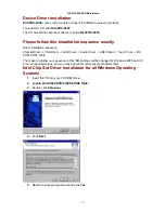
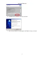
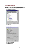
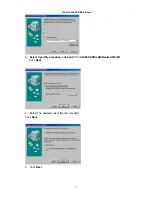
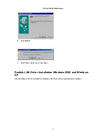
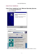
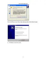
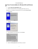
Страница 37: ...FIR ULV600 DVR Main Board 31 5 Click Finish to complete the installation procedure and restart the system...

Страница 38: ...32 Enable second LCD panel setting Windows 2000 Windows XP After you have installed the VGA driver you must adjust the settings 10 Right click your mouse anywhere on the desktop then click properties...

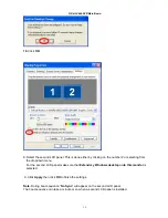
Страница 39: ...FIR ULV600 DVR Main Board 33 12 Click Advanced 13 Click Intel R Extreme Graphics...

Страница 40: ...FIR ULV600 DVR Main Board 34 14 Click Graphics Properties 15 Click Extended Desktop and select Notebook for primary device monitor for secondary device...

Страница 41: ...ecting from the dropdown menu For the second LCD panel make sure that Extend my Windows desktop onto this monitor is selected 9 Click Apply then click OK to finish the settings Note During boot sequen...

Страница 42: ...Board 36 LAN Driver Installation Realtek LAN Driver Installation Windows 98 1 Open Device Manger in the System Properties Select PCI Ethernet Controller Click Properties 2 Select the General tab Clic...

Страница 43: ...FIR ULV600 DVR Main Board 37 3 Select Specifily a location click path C ULV600 DVR LAN Realtek Win98 Click Next 4 Select The updated driver Recommended Click Next 5 Click Next...

Страница 44: ...Main Board 38 6 Click Finish 7 Click Yes to restart your computer Realtek LAN Driver Installation Windows 2000 and Windows XP After Windows 2000 is installed the Realtek LAN driver will be automatica...

Страница 45: ...Installation Audio Driver Installation for all Windows Operating Systems 1 Open D ULV600 DVR AUDIO Realtek 2 double click Setup exe 3 Select Next to continue Note For Windows 2K If you receive this wa...

Страница 46: ...FIR ULV600 DVR Main Board 40 Note For XP If you receive this warning message please click Continue Anyway 4 Click Finish and restart the system...

Страница 47: ...V600 DVR Main Board 41 USB Driver Installation USB 2 0 Installation for Windows 98 ME 1 Open Device Manger in the System Properties Select PCI Universal Serial Bus Click Properties 2 Click Reinstall D...

Страница 48: ...DVR Main Board 42 3 Click Next 4 Select Search a better driver than the one your device is using now Recommended Click Next 5 Select Specify a location click path C ULV600 DVR USB2 0 INTEL WIN98_ME C...

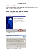
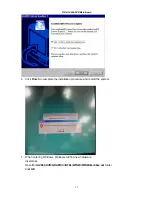
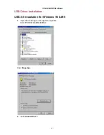
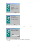
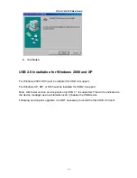
Страница 49: ...FIR ULV600 DVR Main Board 43 6 Click Next 7 Click OK 8 click path C ULV600 DVR USB2 0 INTEL WIN98_ME Click OK...

Страница 50: ...d for USB 2 0 support For Windows XP SP1 or SP2 must be installed for USB 2 0 support Note with lower version service packs only USB 1 1 is supported This will be indicated in the device manager as an...

Страница 51: ...stallation for Windows 98 1 Insert the Utility CD and locate the touch screen folder D Utility TOUCHSCREEN ELO Touch ELO Win 9X_me 2 Run Setup exe 3 Click Next 4 Read the License Agreement and click Y...

Страница 52: ...primary touch screen and COM4 for second touch screen Then click Next 7 Wait until the ELO Touch Tools have been installed 8 Select View ELO touch screen control panel and click Finish 10 Click Yes to...

Страница 53: ...N ELO Touch 2 Select the relevant ELO folder for the operating system that you are using Example If you are installing for a Windows 2000 or XP then select Elo Touch 2K_XP 3 Run Setup exe 4 Click Next...

Страница 54: ...ect Elo devices and click Next 8 Select the COM port for the touch monitor It is recommended that you select COM3 for the touch screen as this port is internally configured for touch operation 9 Wait...

Страница 55: ...ish IT MAY BE NECESSARY TO RESTART YOUR COMPUTER TO UTILIZE YOUR TOUCHSCREEN FEATURES 11 Click NEXT while this window appears after system finishs rebooting 12 Click YES to restart your computer again...

Страница 56: ...0 ELO Control Panel This section explains the different options in the ELO control Panel General tab The general tab allows you to Change the COM port your touch screen is set to Calibrate the touch s...

Страница 57: ...Mode tab The Buttons tab allows you to Adjust all mouse emulation controls Change cursor properties Enable or disable right mouse button utility Sound tab The Sound tab allows you to To change sound p...

Страница 58: ...FIR ULV600 DVR Main Board 52 Properties tab The Diagnostics tab allows you to View Controller Information About tab The About tab displays Information about ELO Touch systems...

Страница 59: ...ms 1 Locate D Utility TOUCHSCREEN TouchKit Driver 2 Select the relevant eGalax folder for the operating system that you are using Example If you are installing for a Windows 98 system then select Win9...

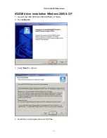
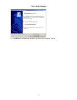
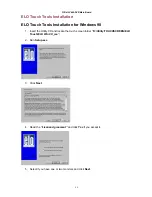
Страница 60: ...FIR ULV600 DVR Main Board 54 6 Click Next 7 Click Next 8 Click Next...

Страница 61: ...FIR ULV600 DVR Main Board 55 9 Click Yes 10 Click Finish to restart your computer again After the system finishes rebooting follow the directions to calibrate the Touch screen...

Страница 62: ...Kit Control Panel This section explains the different options in the TouchKit control Panel General tab The general tab allows you to Change the COM port your touch screen is set to Calibrate the touc...

Страница 63: ...VR Main Board 57 Wireless LAN Driver Installation Wireless LAN Driver Installation for all Windows Operating Systems Optional 1 Open D Utility Wireless LAN 802 11b folder 2 Run Setup EXE 3 Click Next...

Страница 64: ...R SDRAM To the maximum of 1GB VGA controller On chip 852GM built in AGP2 0 4X 3D graphics engine Shares system DDR SDRAM 32MB max Supports 18bit 24bit single pixel or 36bit 48bit dual pixel color LVDS...

Страница 65: ...hrough I O port 280H Keyboard Port One PS 2 keyboard port LAN Port 10 100Mbps Ethernet Controller Realtek RTL8100BL VGA Port Standard VGA Port for second LCD panel Audio Port Integrated Sound Blaster...

Страница 66: ...l 800X600 1024x768 Primary Touch Panel 8 4 ELO 4 wire or 14 1 ELO 5 wire resistive touch panel Compact Flash Disk socket Type I II Compact Flash Disk The Flash Disk provides 100 compatibility with IDE...

Страница 67: ...h BNC Composite Video NTSC PAL SECAM auto sensing Optional Features Customer display Integrated VFD LCD customer display Program keyboard with MCR Integrated 60Key Keyboard with Single Dual Triple Tra...

Страница 68: ...Board Configuration LVDS1 JP10 VGA2 VGA1 CN6 USB1 KB MS CN10 Button LED CN4 J5 JP2 CN5 J4 Power J7 J6 MIC SPK USB2 COM4 COM2 COM1 DIO CF JP7 Power DDR DIMM Socket LAN J3 IDE1 LPT1 COM5 COM6 JP6 JP5 CN...

Страница 69: ...in connector LPT1 Parallel port connector IDE1 Ultra ATA100 Primary IDE connectors CF1 Compact Flash Storage Card Type II connector PS_ON1 Power on Switch LED1 Power LED CN1 PC 104 Plus connector CN2...

Страница 70: ...ode Selection for RS 232 device JP5 Description Short 1 3 CTS Short 2 4 RTS JP5 COM2 RI Function Setting JP6 Description Short 1 2 RI is 5Volt output Short 3 4 RI function Short 5 6 RI is 12 Volt outp...

Страница 71: ...CH2 CLK 19 CH2 DATA2 20 CH2 DATA2 21 CH2 DATA1 22 CH2 DATA1 23 CH2 DATA0 24 CH2 DATA0 25 GROUND 26 GROUND 27 LCD power 28 LCD power 29 LCD power 30 LCD power VGA1 15 Pin Female Connector PIN Descripti...

Страница 72: ...tion 1 VCC 5 VCC 2 DATA0 6 DATA1 3 DATA0 7 DATA1 4 GROUND 8 GROUND COM1 D SUB Serial Port Connector PIN Description PIN Description 1 DCD 6 DSR 2 RXD 7 RTS 3 TXD 8 CTS 4 DTR 9 RI 5 GROUND COM2 D SUB S...

Страница 73: ...I6 19 GROUND6 20 GROUND6 KB_MS1 Mini DIN Keyboard Mouse Connector PIN Description 1 KEYBOARD DATA 2 MOUSE DATA 3 GROUND 4 5V 5 KEYBOARD CLOCK 6 MOUSE CLOCK J4 J5 CPU FAN Case FAN Connector PIN Descrip...

Страница 74: ...GROUND 27 CHRDY 28 REV PULL LOW 29 DACK 30 GROUND 31 INTERRUPT 32 N C 33 SA1 34 PD66 SELECT 35 SA0 36 SA2 37 HDC CS0 38 HDC CS1 39 HDD ACTIVE 40 GROUND 41 5V 42 5V 43 GND 44 N C LPT1 LPT1 Box Header...

Страница 75: ...N C 36 VCC 12 N C 37 IRQ15 13 VCC 38 VCC 14 N C 39 MASTER SLAVE 15 N C 40 N C 16 N C 41 RESET 17 N C 42 IORDY 18 A2 43 DREQ 19 A1 44 DACK 20 A0 45 ACTIVE 21 D0 46 PDIAG 22 D1 47 D8 23 D2 48 D9 24 N C...

Страница 76: ...escription 1 12V 2 12V 3 GROUND 4 GROUND 5 Back Light enable CN7 Multi function connector USB 2 0 and COM3 PIN Description PIN Description 1 5V 2 5V 3 USB USB2 0 4 USB USB2 0 5 USB USB2 0 6 USB USB2 0...

Страница 77: ...Signal routing Jumper mode 1 factory default setting USB2 go directory to CON3 SCSI II Connector reserved for USB wireless LAN J2 J3 3 5 Short 1 3 Short 4 6 Short 2 4 Short USB2 Signal routing Jumper...

Страница 78: ...d LCD Display PIN No Description PIN No Description 1 RED 14 GND 2 12V 15 GND 3 GREEN 16 GND 4 12V 17 GND 5 BLUE 18 GND 6 12V 19 GND 7 DDC DAT 20 GND 8 12V 21 GND 9 HSYNC 22 GND 10 12V 23 GND 11 VSYNC...

Страница 79: ...SR 2 RTS 20 RX 3 DM 3 21 Vcc 4 GND 22 DP 3 5 PVDD 23 PVDD 6 RX0 24 RX0 7 RX1 25 RX1 8 RX2 26 RX2 9 RX CLK 27 RX CLK 10 RX3 28 RX3 11 GND 29 GND 12 GND 30 Vcc 13 GND 31 GND 14 KB CK 32 Vcc 15 KB DA 33...

Страница 80: ...B x2 signal connector connects to the main board CN7 PIN No Description PIN No Description 1 DM 1 6 DSR 2 DP 1 7 TX 3 DM 0 8 RX 4 DP 0 9 NC 5 Vcc 10 RTS CON7 60Keys Keyboard signal connector PIN Descr...

Страница 81: ...600 DVR Main Board 75 P1 4Pin Power Connector PIN Description 1 12V 2 GND 3 GND 4 5V A 4 wire cable connects the P1 of 9000PB0810 the supplies DC 12v and DC 5V power for 60keys Keyboard 1st and 2nd LC...

Страница 82: ...n cable should align with IDE1 on the IDE connector of HDD D Reset CMOS DATA by shorting mainboard JP1 PIN2 and PIN3 for a few seconds Please refer to page49 in the FIR ULV600 DVR User s guide E Check...

Страница 83: ...oller Green LED is blinking If no there is no DC 5V support for the ELO controller or the TouchKit controller from the mainboard E 1 Check that the COM3 cable is properly connected between mainboard C...

Страница 84: ...enabled in the CMOS setup and data is written to COM4 in the application B Check if there is any display when system power is ON if the screen is blank please follow the steps below B 1 Make sure the...

Страница 85: ...ommand send L level for 200ms Refer to FIR ULV600 DVR user s manual page C The mainboard could be defective USB device is not Functioning Properly A Ensure that the USB controller is enabled in the CM...

Отзывы: