background image

Sigma_XT_signs_m3.5.docx 


Page 6 of 14


3.1.2.


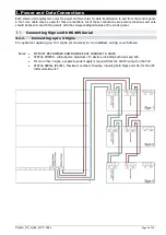
Connecting more than 3 Signs 

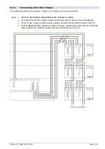
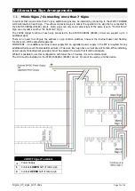
For systems requiring more than 3 signs (or devices), wiring is as follows: 


Notes: 


FIP MUST BE POWERED DOWN BEFORE ANY CHANGES TO SIGNS.  


Connections for the first 3 signs or devices remains the same as the previous wiring diagram. 


For more than 3 signs, a separate power supply is required from the 24VDC output on the FIP. 


STATUS SERIAL (RS485) - Maximum number of devices, including both Signs and LCS, for the 485 
communications is 7. RS485 connection remains the same for all 7 devices. 

Содержание Sigma XT

Страница 1: ...Fire Alarm and System Warning Signs Local Control Stations Installation and Operations Manual Serial Communications Type SIGMA XT FP Issue 3 5 March 2020...

Страница 2: ...CS 7 Power and Data Connection 7 Connection to Hold and Mode inputs 8 Mode input 8 Hold input 8 Mode select keyswitch 8 Manual release 8 Processor and Watchdog Reset Switches 9 Internal fault indicati...

Страница 3: ...tatus units have monitored inputs to which remote Hold or Mode select switches can be connected These inputs are monitored for open and short circuit faults and therefore need to have a 470R 1W trigge...

Страница 4: ...Signs Mount Sunshade Remove cover and Internal circuit board Mount using suitable fixings ONLY Mount to sunshade surface if the enclosure is twisted on mounting it will crack over time Best practice...

Страница 5: ...he corresponding terminals at the control panel Connecting Signs with RS485 Serial 3 1 1 Connecting up to 3 Signs For systems requiring up to 3 signs or devices to be installed wiring is as follows No...

Страница 6: ...WN BEFORE ANY CHANGES TO SIGNS Connections for the first 3 signs or devices remains the same as the previous wiring diagram For more than 3 signs a separate power supply is required from the 24VDC out...

Страница 7: ...r systems requiring a LCS to be installed wiring is as follows Notes FIP MUST BE POWERED DOWN BEFORE ANY CHANGES TO SIGNS If installed as one of the first 3 devices on the STATUS SERIAL RS485 circuit...

Страница 8: ...e inputs Therefore for the system to be in Automatic and manual mode all Mode inputs must be inactive Indication of the Mode is given on the front of the status unit by the Manual only or Automatic an...

Страница 9: ...e located along the bottom of the PCB and are as follows 4 8 1 COM This LED indicates that the data communications connection to the control panel is not present This may be because the data lines are...

Страница 10: ...ERED DOWN BEFORE ANY CHANGES TO DEVICES IMPORTANT Devices with the same address will cause an intermittent fault to be displayed Assigning Sign Function In addition to addressing signs connected to th...

Страница 11: ...utton on the module to view the faults If status units are detected the LCD will display X the address of the status unit found To accept the status units found slide the WRITE ENABLE switch on the mo...

Страница 12: ...p to 3 additional signs There is no need to configure the address or sign function switches however the internal buzzer and flashing functions can still be adjusted separately IMPORTANT An additional...

Страница 13: ...cables for the RS485 circuit with the FIP effectively in the middle of the circuit rather than at one end FIP MUST BE POWERED DOWN BEFORE ANY CHANGES TO SIGNS If process is done with power connected...

Страница 14: ...ame as another device in the 485 circuit Power has failed to the LCS RS485 signal has failed to the LCS 9 Specifications Internal Sign External Sign Local Control Station Size 195 x 300 x 50mm 195 x 3...

Отзывы: