background image

Round Flat Disc

REV. 1-7-19  Page 15

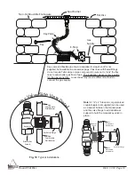
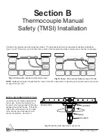
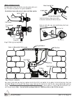
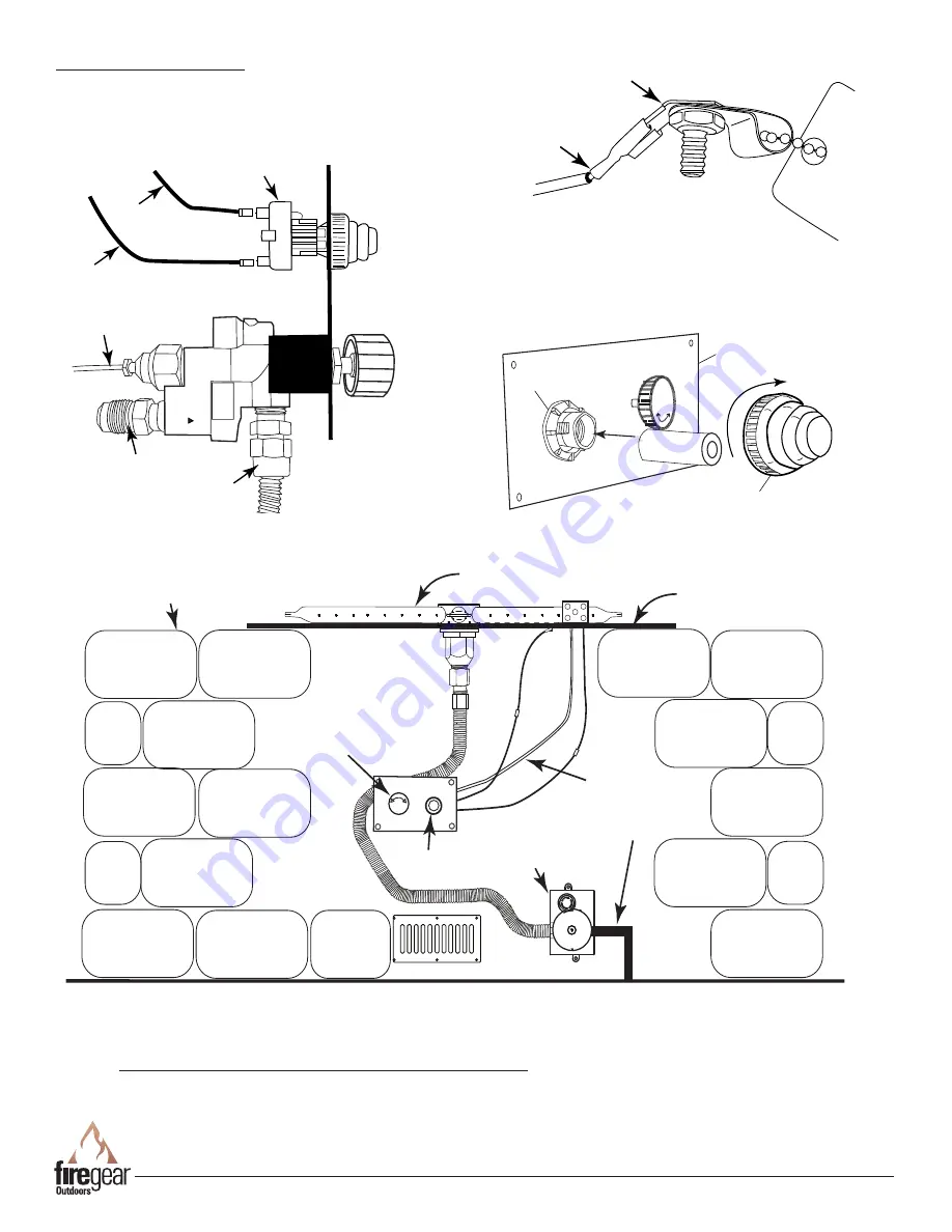
Fig. 17

 TMSI typical installation.

Gas Outlet 

to Fire Pit

Gas Inlet

Thermocouple 

Lead

PIEZO48WH

PIEZO23WH

Ignitor Module

+

-

AAA

Plastic Nut

Red Button Cap

Mounting Plate

Illustration shows side view of valve and Piezo ignitor.

Remove red button cap and install battery into Piezo 

ignitor module.

Piezo Ground Tab

Ratin

g Pla

te

Bottom of Burner Pan

PIEZO48WH

Illustration above shows ground tab 

connection underneath the burner pan.

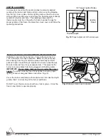
INSTALLING GAS VALVE 

The gas valve is secured into the mounting plate with a nut.     

Fig. 17 shows an example of a typical installation. 

Gas Supply

 Flat Disc

Non-Combustible Enclousure

E-Stop

Spur Burner

OFF

Gas Valve

TC Wire

Piezo

PUSH TO STOP
TURN TO START

OFF

0.5

HOURS

1.5

2

2.5

Gas valve and flexible gas lines are supplied; E-stop shut-off is not supplies, but available in accessories page. Flex lines 

with flared fittings do not require Teflon tape or pipe compound. Ensure not to “kink” the flex lines to allow better gas flow 

of gas.   The illustration above is only a guide for the gas connection.  Local codes may require different methods to con-

nect the gas supply. 

Note:  See optional mounting method of TMSI face plate on back of this manual.

Fig. 18

 Typical installation.

Содержание FPB-26DBSMT-N-SAN

Страница 1: ...FERENCE Warning For Outdoor Use Only INSTALLATION PRECAUTION This fire pit requires a minimum 18 square inches per side of cross ventilation Failure to provide proper ventilation can void the warranty Natural Gas Description FPB 26DBSMT N SAN 26 Round Flat Disc MT system FPB26DBSTMSIN SAN 26 Round Flat Disc TMSI system FPB 34DBSMT N SAN 34 Round Flat Disc MT system FPB34DBSTMSIN SAN 34 Round Flat ...

Страница 2: ...tment DANGER WARNING Do not store or use gasoline or other flammable vapors and liquids in the vicinity of this or other appliances Any LP cylinder not connected for use shall not be stored in the vicinity of this or other appliances WARNING Do not leave unattended during use Do not use for cooking Follow all gas leak procedures in this manual prior to operation WARNING Improper installation adjus...

Страница 3: ...tial to crack or pop outside the fireplace WE HIGHLY RECOMMEND COVERING ALL FIRE FEATURES WHEN NOT IN USE The use of a cover can lessen the impact of thermal spalling however heavy rains high humidity and the presence of moisture may still cause the media to pop ALWAYS USE CAUTION WHEN USING THE FIRE FEATURE Extra caution should be taken when lighting a fireplace when heavy rains high humidity and...

Страница 4: ...fect Btu s As a result your Btu s may vary slightly from Table 2 specifications Table1 Disc Specifications Fig 1 Flat Disc Dimensions refer to Table 1 Model Natural Gas NG A Disc Depth B Pan Diameter C Min Install Opening D Ground Level E Side Wall F Combustible Ceiling G Combustible Floor FPB 26DBSMT N SAN 1 16 26 26 1 2 12 19 69 12 FPB26DBSTMSIN SAN 1 16 26 26 1 2 12 19 69 12 FPB 34DBSMT N SAN 1...

Страница 5: ...for the amount of BTU s for a new gas line installations If you are using an existing gas line you must take into consideration the existing gas line capacities to ensure you will have proper pressure This chart is for reference only we recommend you consult with a Licensed Plumber Gas Fitter or NFPA54 National Fuel Gas Code current edition for more details Length of Pipe in Feet 1 2 3 4 1 1 1 4 1...

Страница 6: ...r pipe sizing See gas pipe sizing chart on page 5 1 Turn OFF gas supply system NOTE All gas connections except for brass to brass require the following Clean pipe threads using either a wire brush or steel wool Apply pipe sealant to the fittings before making any connection BE CAREFUL Ensure all gas connections are snug but do not over tighten 2 The primary gas shut off not supplied will require a...

Страница 7: ...AUTION A minimum of 18 square inches of cross ventilation per side is required to keep the inside of the enclosure dry We recommend installation of a VENT KIT 6x12 See accessory section 8 These products are designed for outdoor use only Not approved for any indoor use 9 This fire pit is designed to have lava rock completely covering the spur burner so that the burner is not visible Do not cover mo...

Страница 8: ...REV 1 7 19 Page 8 Round Flat Disc Section A Match Light MT Installation ...

Страница 9: ...ce hole in the non combustible enclosure wall See the instructions supplied with the key valve for more specific details Note Be sure to leak test all fitting before operation Fig 10 shows an example of a typical installation Primary Gas Supply O N O F F Fig 9 Key valve components Flat disc s are typically used with landscape blocks The illustrations below show examples of possible installations F...

Страница 10: ...Flange Non Combustible Wall Material Non Combustible Wall Material Key Valve Black Iron Nipple Key Valve Gas Supply Flat Disc Non Combustible Enclousure E Stop Spur Burner Key PUSH TO STOP TURN TO START OFF 0 5 HOURS 1 1 5 2 2 5 Key valve and flexible gas line are supplied E stop shut off is not supplied but available in accessories page Flex lines with flared fittings do not require Teflon tape o...

Страница 11: ...fore each use of the appliance 6 Temporary storage of this appliance indoors is permissible only if it has been disconnected from its fuel supply Natural or L P gas line WARNING 1 This appliance is hot when operated and can cause severe burns if contacted 2 Do not burn any solid fuels in this appliance LIGHTING INSTRUCTIONS Key Fig 12 Inserting Key into Valve O N O F F Fig 11 Key Valve Face Butane...

Страница 12: ...rts can discolor when heated usually a golden or brown hue This discoloration is normal and does not affect the performance of the appliance MT TROUBLE SHOOTING SECTION A Symptom Remedy Fire pit won t light 1 Bleed gas line 2 Ensure all gas supply lines are turned ON 3 Ensure there is not too much media overtop of burner it can inhibit gas from flowing 4 Check gas pressure Low flame 1 Ensure the b...

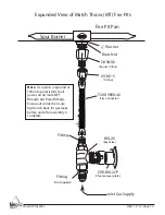
Страница 13: ... Key Valve Fitting Fire Pit Pan Inlet Gas Supply Expanded View of Match Throw MT Fire Pits T200 9898 46 Flex Connector Note Use joint compound or Teflon tape resistant to all gasses on all male NPT threads not flared fittings Ensure all connections are tight and check for gas leaks before and after assembly is complete Not Supplied Fitting ...

Страница 14: ... 16 Fig 16 Installing OAS assembly to spur burner Section B Thermocouple Manual Safety TMSI Installation Fig 14 Shows disc secured under stone caps Fig 15 Shows disc secured between layer of block NOTE Additional methods of supporting the center of the disc underneath or supporting an oversized opening are shown on page 9 in Figs 6 7 Flat disc s are typically used with landscape blocks The illustr...

Страница 15: ... mounting plate with a nut Fig 17 shows an example of a typical installation Gas Supply Flat Disc Non Combustible Enclousure E Stop Spur Burner OFF Gas Valve TC Wire Piezo PUSH TO STOP TURN TO START OFF 0 5 HOURS 1 1 5 2 2 5 Gas valve and flexible gas lines are supplied E stop shut off is not supplies but available in accessories page Flex lines with flared fittings do not require Teflon tape or p...

Страница 16: ... but do not make the depth greater than 1 inch overtop of the burner portholes Do NOT cover the screen mesh with any rock or glass It must be free an any debris to operate properly It is important check that the ignitor probes be properly aligned overtop of the burner port holes and did not move during shipping Use the Fig 19 as a guide Before lighting remove the screen cover of the ignition hood ...

Страница 17: ...orage of this appliance indoors is permissible only if it has been disconnected from its fuel supply Natural or LP gas line WARNING 1 This appliance is hot when operated and can cause severe burns if contacted 2 Do not burn any solid fuels in this appliance Fig 21 Control knob and Piezo button READ ALL LIGHTING INSTRUCTIONS BEFORE ATTEMPTING TO LIGHT FIRE PIT CAUTION ENSURE YOU HAVE LEAK TESTED TH...

Страница 18: ...re all gas supply lines are turned ON 3 Ensure there is not too much media overtop of burner it can inhibit gas from flowing Low Flame 1 Ensure the base media is at least 1 inch in diameter and top media is no more than 1 inch over top of burner 2 Ensure all shut off valves and valve is fully open 3 Check for spider webs inside burner orifice Water In My Fire Pit 1 Excess dust sand material from m...

Страница 19: ...sses on all male NPT threads not flared fitting side Ensure all connections are tight and check for gas leaks before and after assembly is complete REV 1 4 19 Flare to 3 8 Male Thread Fitting Not Supplied U1 8C S Fitting Knob Mounting Nut Inlet Gas Supply Thermocouple PIEZO48WH PIEZO23WH Ignition Module Ground Expanded View of Thermocouple Manual Safety TMSI Fire Pit Ignition Hood Spur Burner ...

Страница 20: ...REV 1 7 19 Page 20 Round Flat Disc ROUND FLAT DISC REPLACEMENT PARTS 1 2 7 8 Drawings are not to scale 9 10 11 12 21 4 6 3 5 22 23 20 PIEZO48WH PIEZO25WH Inlet Outlet 13 14 15 16 17 18 19 24 25 ...

Страница 21: ...110 1005 x 13 Manual Gas Valve Control Knob 1 ST3 050 1024 x 14 Manual Gas Valve TMSI 1 ST3 080 1009 x 15 Piezo Ignition Module includes plastic nut red button 1 3042 RB x 16 Flare x Brass Elbow Used on BVL2S 2 49 88 x 17 Key Valve manual shut off valve 1 BVL2S x 18 Chrome Cover Plate 1 CVR BVL2CP x 19 MT Key Valve Face Plate 1 MT FACEPLATE x 20 Ignition Hood for Spur Burner 1 SPURHOOD x 21 Mesh S...

Страница 22: ...Flare Vent Kits Provide 18 sq in of ventilation per side of enclosure Model VENT KIT 6X12SS Model PAVER VENT 4LNTS Model PAVER VENT 6LNTS Paver Control Panels Models PAVER CP MT MT systems PAVER CP TMSI TMSI systems E STOP Mechanical gas timer valve with emergency shut off Model ESTOP1 0H 1hr timer Model ESTOP2 5H 2 5hr timer Not for use with TFS fire pit systems Log Sets Model L SF Spit Fire 17pc...

Страница 23: ... location or failure to perform normal and routine maintenance Damage due to severe weather conditions such as hail hurricanes earthquakes tornadoes discoloration due to over heating exposure to chemicals including salt either directly or in the atmosphere or very high humidity is not covered by this Limited Warranty There are no other express warranties except as set forth herein For consumer app...

Страница 24: ...O LIGHT Position 2 Position 1 Position 3 The TMS valve bracket can be oriented in different positions to accommodate different installations Once the bracket and knob are installed the knob may not be oriented in a convenient position to easily read If this is the case we have provided a label that can be placed over top of the existing knob for the user to easily know which way to turn the contro...

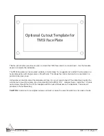
Страница 25: ... gas valve on the left side This allows the control knob text to be orientated in a position to be easily read Using scissors carefully cutout the template and trace it on your concrete board The dotted line provides the cutout area to mount face plate Use a concrete drill bit to drill 4 3 16 diameter holes Install the 1 black oxide screws through the front of the faceplate with the nuts and washe...

Страница 26: ..._____________ 2 Serial Number ___________________________ 3 How long is the gas line run Nat Gas ____ LP Gas ____ 4 What size is gas line _____ 5 Inlet Gas Pressure _____WC Manifold Gas Pressure _____ WC 6 What type of media are you using __________________ 7 Review the troubleshooting section in the installation manual 8 What are the symptoms Please be prepared to explain 9 Be prepared to send ph...

Отзывы: