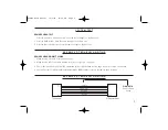
Firecom 3010R Скачать руководство пользователя страница 2

SYSTEM OVERVIEW

This manual provides an overview of the 3010R Series Intercom System and an introduction to its individual components. Figure 1
shows a typical system. Refer to this diagram for each component.

REMOTE HEAD

The base unit has the ability to be remotely controlled by up to two remote heads. These panels function the same as the base
unit front panel. Regardless of which button is pressed, all units will respond and update at the same time. Power to the unit is
supplied through the CA cable from the intercom. The remote head can be mounted 

INSIDE

the apparatus either flush on a

surface or with a special bracket.

INTERCOM

The main control unit for the 3010R Series Intercom System which contains all the controls and interface circuitry.

2-WAY RADIO

The existing 2-way radio in the apparatus. 

MOBILE RADIO INTERFACE CABLE

Provides the interface connections between the 3010R Series Intercom Unit and the 2-way radio in the apparatus. There are
many different cable assemblies available; the particular cable needed depends on the make and model of your radio. Contact
your local Firecom dealer for more information regarding an interface cable specific to your radio.

POWER CABLE ASSEMBLY

Provides the power connections for the 3010R Series Intercom Unit. The power connections should be made at the same place
as the power connections for your radio.

HM-10 HEADSET MODULES

Headsets are plugged into the headset modules to interface them into the system. The HM-10 is the standard headset module
for use inside the apparatus.

PP-20 PUMP PANEL MODULE

A water-resistant headset module for use on the exterior of the apparatus (e.g. at the pump panel, at the tail-board, etc.).

S Y S T E M O R I E N T A T I O N

Remote Head Manual  12/4/03  10:06 AM  Page 2

Содержание 3010R

Страница 1: ...3025R 3020R 3015R 3010R FIRE APPARATUS INTERCOM REMOTE HEAD 3025 REMOTE HEAD I N S T A L L A T I O N O P E R A T I O N M A N U A L Remote Head Manual 12 4 03 10 06 AM Page 1...

Страница 2: ...2 way radio in the apparatus MOBILE RADIO INTERFACE CABLE Provides the interface connections between the 3010R Series Intercom Unit and the 2 way radio in the apparatus There are many different cable...

Страница 3: ...I O N CA CABLES Six conductor flat cable which connects the 3010R Series Intercom Unit to the HM 10 PP 20 headset modules and the remote heads FIGURE 1 3010R Series System Overview 1 Remote Head Manu...

Страница 4: ...he 3020R Intercom REMOTE CONTROL 3025R Part Number 108 1325 00 This will control the 3025R Intercom BRACKET ASSEMBLY Part Number 108 0303 00 Remote Kit MODEL 3015R Intercom Communication Single Radio...

Страница 5: ...aying a message that has been recorded by the digital message recorder DMR PLAY LED 3015R 3025R ONLY A green LED which indicates the digital message recorder is playing a recorded message RECORD LED 3...

Страница 6: ...in 4 directions Flush to the outside of the mounting plane in the up down and right side direction or through the mounting plane on the back When exiting up down and right a small wire groove is prov...

Страница 7: ...the CA cable to the bracket anchors as shown in Figure 6 10 Before installing the bracket to the mounting surface drill a 3 4 hole at the wire location Snap the grommet into the bracket as shown in F...

Страница 8: ...se tab on the plug locks into position 7 Holding the cable so that the printed side of the cable is toward the release tab on the plug push the cable into the plug as far as it will go ALWAYS make sur...

Страница 9: ...A cable is inserted all the way 2 Make sure the cable ends were installed correctly see Figure 9 on page 6 3 Check that the ribbon cable from the membrane switch is fully inserted into the edge connec...

Страница 10: ...does not extend to any other equipment or apparatus to which this product may be attached or connected The foregoing is your sole remedy for failure in service or defects Sonetics Corporation shall no...

Отзывы: