


22
Application, Installation & Commissioning Doc. version 2
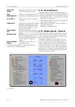
3.14 Internal Buzzer
FIRECLASS Prescient III
The Algemeen Storing LED on the Display board also
pulses for any of the above faults.
3.14 Internal Buzzer
The internal buzzer provides an audible indication to
compliment the visual indications provided via the LEDs
on the panel. The buzzer has various modes as follows:
1
Fault Indication - Pulse, 1 second On, 3 seconds OFF
The buzzer can be silenced.
2
Alarm Indication - Pulse, 1 second On, 1 second OFF
The buzzer can be silenced.
3
Buzzer Pulse End Of Delay - Pulse, ½ second On, ½
second OFF (Optional)
The buzzer cannot be silenced.
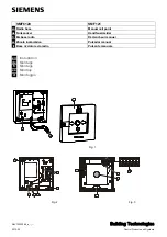
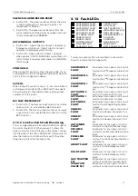
3.15 Display Board - General
The Display board is connected to the internal control
board via a 16-way ribbon cable and polarised ribbon
socket. A polarised 16-way header is provided on the
main control board at position J1.
The Display is divided into three windows for clarity.
BEDIENING
buttons are positioned in the central win-
dow, with Status LEDs in the left & right windows.
The left window displays the status of the Fire Alarm
section of the panel, as well as indications which are
common to both the Fire Alarm section and the Extin-
guishing section. The right window is dedicated to dis-
playing the status of the Extinguishing section of the
panel. See Figure 5 for details.
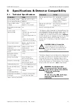
GAS LOW
FAULT
Illuminates for any open or short cir-
cuit fault on the Gas Low input.
GAS
RELEASED FLT
Illuminates for any open or short cir-
cuit fault on the Gas Released input.
SLU FAULT
Illuminates for a fault on any Status
Lamp Unit.
CONFIG ON
Illuminates when either the CONFIG
I/S INPUTS or the CONFIG SLU DIL
switch is in the ON position. It indi-
cates that the EEPROM on control
board is write-enabled.
GAS SIGNAL
FLT
Illuminates for any open or short cir-
cuit fault on the Gas Released Signal
output.
MAINS FAULT
Illuminates if the AC mains input volt-
age to the power supply is lost or is
less than the required minimum for
correct operation of the power
supply.
BATT/CHARGE
FAULT
Illuminates for any of the faults
described in section.
Fig. 5: Display
STATUS BRAND
SYSTEEM STATUS
BEDIENING
STATUS BLUSSING
BRAND
DOORMELDING BRAND
GROEP 1
GROEP 2
EXTERNE GROEP
EXTERNE ALARM INPUT
STORING EXTERNE INPUT
SIGNAALGEVERS; STORING/UIT
IN BEDRIJF
ALGEMEEN STORING
VOEDING STORING
SYSTEEM STORING
AARD FOUT
ZEKERING DEFECT
DOORM. STORING; STORING/UIT
SIGNAALGEVER TEST
AUTOMATISCH & HANDBEDIENING
HANDBEDIENING
HANDACTIVERING
SYSTEEM AKTIEF
BLUSSING AKTIEF
DOORMELDING BLUSSING
BLUSSING GEBLOKKEERD
UITSTEL BLUSSING
BLUSSTURING STORING
LAGE DRUK GASCILLINDERS
HOGE DRUK VERZAMELLEIDING
AFSLUITER ONJUIST
AFSLUITER DICHT
HANDACTIVERING; STORING/UIT
BLUSSING UIT
DOORM. BLUSSING; STORING/UIT
ALGEMENE STURINGEN UIT
BLUSVER-
TRAGING
SIGNAAL
GEVERS
UIT
HERSTEL
BRAND-
ALARM
ZOEMER
UIT
SELECTEER
AAN/UIT
SELECT
UIT
BEDIENING
AAN
TEST
UITSCHAK-
ELEN
INSCHAK-
ELEN
AUTO & HAND/
ALLEEN HAND
HERSTEL
BLUSSING
(GEBLOKKEERD)
SIGNAAL
GEVERS
AAN