background image

ECC-FFT Instruction Manual —

 P/N LS10031-000FL-E:B  9/4/2013

13

Installing the ECC-FFT

Installation

2.3  Installing the ECC-FFT

2.3.1  Operating Power

Connect the ECC-FFT to the appropriate DC power source. See Section 1.3 for compatible equip-
ment and Section 1.5 for power requirements.

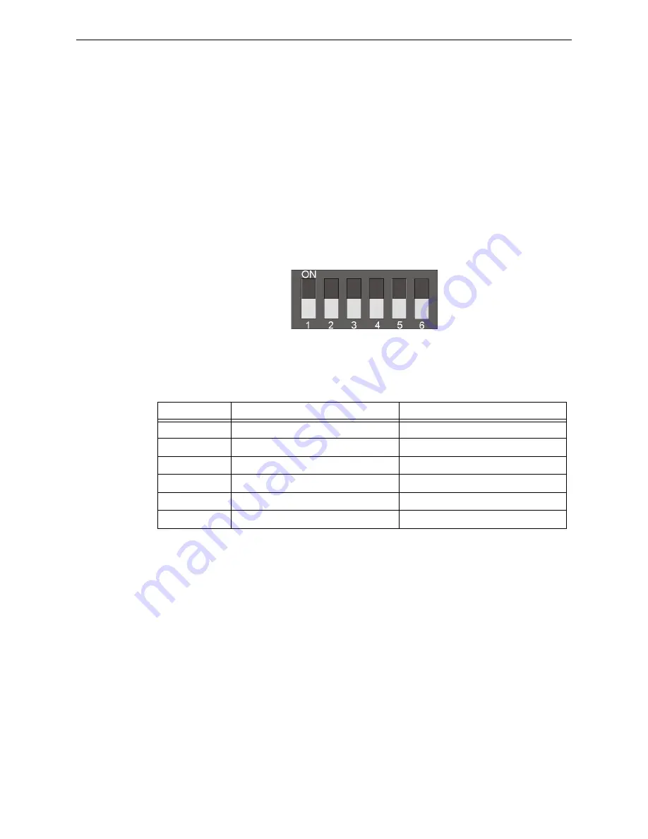
2.3.2  DIP switch settings on ECC-FFT

Use the on-board DIP switch to assign the configuration setting to the ECC-FFT.

1. Refer to Figure 2.3 for location of the DIP switches on the ECC-FFT board.
2. Configure the ECC-FFT using the dip switch settings in Table 2.1. Add SLC modules to the 

system through Autoprogram feature. See Section 3.3 for Autoprogram Operation.  

DIP Switch


DIP Switch

ON

OFF

1

SLC Devices Installed

SLC Devices not Installed

2

Trouble Piezo Enabled

Trouble Piezo Disabled

3

SLC Class A Supervision

SLC Class B Supervision

4

Phone Circuit Class A Supervision

Phone Circuit Class B Supervision

5

Not Used

Leave in OFF position

6

Not Used

Leave in OFF position

Table 2.1  ECC-FFT DIP Switch Configurations

Figure 2.3  DIP Switch

Содержание ECC-FFT

Страница 1: ...B P N LS10031 000FL E B ECN 13 707 Document LS10031 000FL E 9 4 2013 Rev Firefighter s Telephone ECC FFT Instruction Manual ...

Страница 2: ...e warning of a fire Smoke detectors cannot be expected to provide adequate warn ing of fires caused by arson children playing with matches especially in bedrooms smoking in bed and violent explosions caused by escaping gas improper storage of flammable materi als etc Heat detectors do not sense particles of combustion and alarm only when heat on their sensors increases at a predetermined rate or r...

Страница 3: ...ny problems are anticipated or encoun tered Disconnect AC power and batteries prior to removing or inserting circuit boards Failure to do so can damage circuits Remove all electronic assemblies prior to any drilling filing reaming or punching of the enclosure When possible make all cable entries from the sides or rear Before making modifi cations verify that they will not interfere with battery tr...

Страница 4: ...propriate version for a specific application Documentation Feedback Your feedback helps us keep our documentation up to date and accurate If you have any comments or suggestions about our online Help or printed manuals you can email us Please include the following information Product name and version number if applicable Printed manual or online Help Topic Title for online Help Page number for pri...

Страница 5: ...stallation 16 2 7 SLC Device Installation 17 2 7 1 List of SLC Devices 17 2 7 2 Maximum Number of Devices 17 2 7 3 Wiring Requirements for SLC Device 17 Wiring SLC in Style 4 Class B Configuration 17 Wiring SLC Devices in Style 6 7 Class A Configuration 19 2 7 4 Addressing MMF 301 SLC Devices 19 2 8 Audio Phone Circuit Installation 20 2 8 1 Maximum Number of Devices 20 2 8 2 Wiring Requirements fo...

Страница 6: ...Fire Protective Signaling Systems UL 1481 Power Supplies for Fire Protective Signaling Systems UL 1638 Visual Signaling Appliances UL 1711 Amplifiers for Fire Protective Signaling Systems UL 1971 Signaling Devices for Hearing Impaired UL 2572 Communication and Control Units for Mass Notification Systems NEC Article 250 Grounding NEC Article 300 Wiring Methods NEC Article 760 Fire Protective Signal...

Страница 7: ...et Cabinet FHSC RF SF is used to store up to five 5 Fire Fighter Handsets FHS F System Status LEDs 1 2 Optional Accessories This manual also contains information on how to install the following compatible accessories with the FFT series equipment 1 3 Compatible Devices Table 1 1 lists the available FireLite fire alarm control panels systems and power supplies compati ble with the ECC FFT Model Num...

Страница 8: ...the cab inet Then lift the control board out of the cabinet ON 1 2 3 4 5 6 SLC OUT SLC IN PHONE OUT PHONE IN A B TROUBLE NO COM NC 1 2 3 4 Autoprogram Accept Status LEDs Local Handset piezo Phone In Phone Out SLC IN SLC Out mounting stud mounting studs Supervised Power Limited All circuits are inherently power limited except the trouble relay Not Used DC Power System Trouble Relay Non Power Limite...

Страница 9: ... range of 17 29 VDC 1 5 2 Current Ratings Maximum current ratings for determining backup battery requirements for alarm active and standby conditions over the input voltage range of 17 29 VDC are shown in Table 1 3 below Zone 1 Zone 8 Zone 9 Zone 16 Zone 17 Zone 24 Figure 1 2 ECC FFT Keypad eccfftkypd wmf Circuits Voltage Current SLC Circuit 32 V 150 mA Audio Circuits 17 V 53 mA Trouble Relay 12 V...

Страница 10: ...same conduit If you must run them together do so for as short a distance as possible or use shielded cable Twisted shielded wire on the Audio Circuits is recommended for maximum protection against EMI and AFI emissions and susceptibility Connect the shield to earth ground at the panel You must route high and low voltages separately Route the wiring around the inside perimeter of the cabinet It sho...

Страница 11: ... with the National and or Local codes for fire alarm systems 2 2 Backbox Installation 1 Open the door and lift the door off the pin hinges 2 Loosen the two 2 screws that secure the dress panel to the backbox Then lift up to swing the dress panel open 3 Disconnect the ground wire from the dress panel 4 Lift the dress panel up and gently pull the lower hinge out of the backbox Gently pull down to re...

Страница 12: ...assembly and dress panel by reversing the steps above Use appropriate precautions to prevent damage to components due to static discharge 11 Draw wires through the respective knockout locations An optional Trim Ring P N TR CE is available for semi flush mount installations Figure 2 2 Cabinet Dimensions Knockout Locations 9050udencl wmf Semi Flush Mounting Do not recess box more than 3 875 into wal...

Страница 13: ... Figure 2 3 for location of the DIP switches on the ECC FFT board 2 Configure the ECC FFT using the dip switch settings in Table 2 1 Add SLC modules to the system through Autoprogram feature See Section 3 3 for Autoprogram Operation DIP Switch DIP Switch ON OFF 1 SLC Devices Installed SLC Devices not Installed 2 Trouble Piezo Enabled Trouble Piezo Disabled 3 SLC Class A Supervision SLC Class B Sup...

Страница 14: ...t wiring must remain at least 0 25 6 35 mm away from any nonpower lim ited circuit wiring and nonpower limited circuit wiring must enter and exit the cabinet through dif ferent knockouts and or conduits A typical wiring diagram for the ECC FFT is shown below Figure 2 4 UL Power Limited Wiring Requirements back view of dress panel Note The dress panel is shown swung open for illustration purposes o...

Страница 15: ...ephone remote handset FHS F into the FPJ F which is then displayed on the ECC FFT active zone LED during the Autoprogram fea ture 0 10 11 12 13 14 15 ADDRESS LOOP 1 2 3 4 TENS ONES 6 7 8 9 5 0 1 2 3 4 6 7 8 9 5 TB1 TB2 3 2 1 1 2 3 To FFT SLC Terminal TB4 Connectors or other MMF 301 The wiring between the monitor module and FPJ F is supervised by the monitor module A 47K End of Line resistor is bui...

Страница 16: ... telephone audio loop between the FPJ F and FFT as detailed below All circuits are power limited and supervised Figure 2 6 FPJ F Phone Jack and FHS F Handset 0 10 11 12 13 14 15 ADDRESS LOOP 1 2 3 4 TENS ONES 6 7 8 9 5 0 1 2 3 4 6 7 8 9 5 TB1 TB2 3 2 1 1 2 3 SLC PHONE PHONE OUT OUT IN IN SLC Figure 2 7 FFT to FPJ F Connection Class A wiring Audio Audio To FFT SLC terminal TB4 connectors or other M...

Страница 17: ...ration No special wire is required for the ECC FFT SLC loop The wire can be untwisted unshielded solid or stranded as long as it meets the National Electric Code 760 51 requirements for power lim ited fire protective signaling cables Wire distances are computed using copper wire Maximum wiring resistance is 40 ohms to the farthest SLC device Maximum loop length depends on the wire gauge WARNING RI...

Страница 18: ...Wire Run Length The dotted line path shows how the wire distance is calculated for the SLC device at the end of the run The wire distance must be less than the maximum per wire gauge SLC device SLC device SLC device SLC device max loop resistance 40 ohms SLC Circuit Figure 2 9 Calculating Wire Run Length for a T tap In this example 1000 feet 1600 feet 3500 feet 16 AWG wire can be used because the ...

Страница 19: ...uire the use of short circuit isolator devices MM ISO ISO ISO ISO ISO ISO ISO ISO ISO ISO ISO ISO MM MM MM MM MM ISO SLC Device Mini monitor module MMF 301 Isolator Device I300 MM ISO ISO MM MM MM MM MM MM MM SLC Circuit SLC Circuit SLC IN SLC OUT SLC IN SLC OUT Note A maximum of 20 isolator modules can be attached to the ECC FFT Style 6 Wring Style 7 Wring Figure 2 10 Class A SLC Configuration Wi...

Страница 20: ... minimum of one Fire Fighter Telephone Jack FPJ F 2 8 2 Wiring Requirements for the Audio Telephone Circuit No special wire is required for the Audio Telephone Circuit The wire can be untwisted unshielded twisted or shielded as long as it meets the National Electric code 760 51 requirements for power limited fire protective signaling cables 54 Ohm maximum impedance 12 to 18 AWG Twisted shielded wi...

Страница 21: ... 2 3 4 6 7 8 9 5 0 10 11 12 13 14 15 ADDRESS LOOP 1 2 3 4 TENS ONES 6 7 8 9 5 0 1 2 3 4 6 7 8 9 5 0 10 11 12 13 14 15 ADDRESS LOOP 1 2 3 4 TENS ONES 6 7 8 9 5 0 1 2 3 4 6 7 8 9 5 TB1 TB2 3 2 1 1 2 3 TB1 TB2 3 2 1 1 2 3 TB1 TB2 3 2 1 1 2 3 SLC PHONE PHONE OUT OUT IN IN SLC Contact EOL Connected Audio Audio SLC SLC Caution For system supervision For terminals 2 and 3 do not use looped wire under ter...

Страница 22: ...10 11 12 13 14 15 ADDRESS LOOP 1 2 3 4 TENS ONES 6 7 8 9 5 0 1 2 3 4 6 7 8 9 5 0 10 11 12 13 14 15 ADDRESS LOOP 1 2 3 4 TENS ONES 6 7 8 9 5 0 1 2 3 4 6 7 8 9 5 TB1 TB2 3 2 1 1 2 3 TB1 TB2 3 2 1 1 2 3 TB1 TB2 3 2 1 1 2 3 SLC PHONE PHONE OUT OUT IN IN SLC Figure 2 12 Single Phone Jack Audio Circuit in Class A Contact EOL Connected Audio Audio Audio Audio SLC SLC Caution For system supervision For te...

Страница 23: ...9 5 0 1 2 3 4 6 7 8 9 5 0 10 11 12 13 14 15 ADDRESS LOOP 1 2 3 4 TENS ONES 6 7 8 9 5 0 1 2 3 4 6 7 8 9 5 TB1 TB2 3 2 1 1 2 3 TB1 TB2 3 2 1 1 2 3 TB1 TB2 3 2 1 1 2 3 TB1 TB2 3 2 1 1 2 3 TB1 TB2 3 2 1 1 2 3 TB1 TB2 3 2 1 1 2 3 SLC PHONE PHONE OUT OUT IN IN SLC Audio Audio Caution For system supervision For terminals 2 and 3 do not use looped wire under terminals Break wire run to provide supervision...

Страница 24: ...S LOOP 1 2 3 4 TENS ONES 6 7 8 9 5 0 1 2 3 4 6 7 8 9 5 0 10 11 12 13 14 15 ADDRESS LOOP 1 2 3 4 TENS ONES 6 7 8 9 5 0 1 2 3 4 6 7 8 9 5 TB1 TB2 3 2 1 1 2 3 TB1 TB2 3 2 1 1 2 3 TB1 TB2 3 2 1 1 2 3 TB1 TB2 3 2 1 1 2 3 TB1 TB2 3 2 1 1 2 3 TB1 TB2 3 2 1 1 2 3 SLC PHONE PHONE OUT OUT IN IN SLC Audio Audio Audio Audio Caution For system supervision For terminals 2 and 3 do not use looped wire under term...

Страница 25: ...tion 1 must be off SLC Devices not Installed See Table 2 1 on page 13 Audio wiring for this configuration is detailed below See Figures 2 15 and 2 16 TB1 TB2 3 2 1 1 2 3 TB1 TB2 3 2 1 1 2 3 TB1 TB2 3 2 1 1 2 3 SLC PHONE PHONE OUT OUT IN IN SLC Audio Audio Caution For system supervision For terminals 2 and 3 do not use looped wire under terminals Break wire run to provide supervision of connections...

Страница 26: ...TB2 3 2 1 1 2 3 TB1 TB2 3 2 1 1 2 3 SLC PHONE PHONE OUT OUT IN IN SLC Figure 2 16 Telephone Jack Only Audio Circuit in Class A Audio Audio Audio Audio Caution For system supervision For terminals 2 and 3 do not use looped wire under terminals Break wire run to provide supervision of connections FPJ F FPJ F FPJ F FFT Class A Wiring ...

Страница 27: ...nnected to the phone circuit simultaneously After the initial remote handset the connection of additional handsets does not cause the piezo to sound or the Answer Call LED to blink Trouble Silence The Trouble Silence button is used to silence a system type trouble that has occurred in the FFT system Once pressed the piezo will silence 3 2 LED Operations Power Status LED on Inside of FFT dress pane...

Страница 28: ...ressing the Trouble Silence Key will cause the zone trouble LED to turn on steady Once the zone trouble is corrected the LED will turn off 3 3 Autoprogram Operation The Autoprogram feature will attempt to locate all SLC Mini Monitor devices installed in the sys tem indicate all devices found on the FFT and allow the user to accept the configuration repeat the Autoprogram or allow the configuration...

Страница 29: ...the keypad buttons as desired and slide the labels in The labels slide upwards through the slits in the bottom of the keypad covering the white spaces Zone 1 Zone 2 Zone 3 Zone 4 Zone 5 Zone 6 Zone 7 Zone 8 Zone 9 Zone 10 Zone 11 Zone 12 Zone 13 Zone 14 Zone 15 Zone 16 Zone 17 Zone 18 Zone 19 Zone 20 Zone 21 Zone 22 Zone 23 Zone 24 ...

Страница 30: ...30 ECC FFT Instruction Manual P N LS10031 000FL E B 9 4 2013 Slide in Labels Autoprogram Operation ...

Страница 31: ...IED WITH RESPECT TO THE PRODUCTS TRADEMARKS PROGRAMS AND SERVICES RENDERED BY MANUFACTURER INCLUDING WITHOUT LIMITATION INFRINGEMENT TITLE MERCHANTABILITY OR FITNESS FOR ANY PARTICULAR PURPOSE MANUFACTURER SHALL NOT BE LIABLE FOR ANY PERSONAL INJURY OR DEATH WHICH MAY ARISE IN THE COURSE OF OR AS A RESULT OF PERSONAL COMMERCIAL OR INDUSTRIAL USES OF ITS PRODUCTS This document constitutes the only ...

Страница 32: ...World Headquarters 1 Firelite Place Northford CT 06472 1653 USA 203 484 7161 fax 203 484 7118 www firelite com ...

Отзывы: