Emergency Command Center Manual —
P/N LS10001-000FL-E:D 9/3/2014
75
Programmed Activation by FACP
Programming
1.
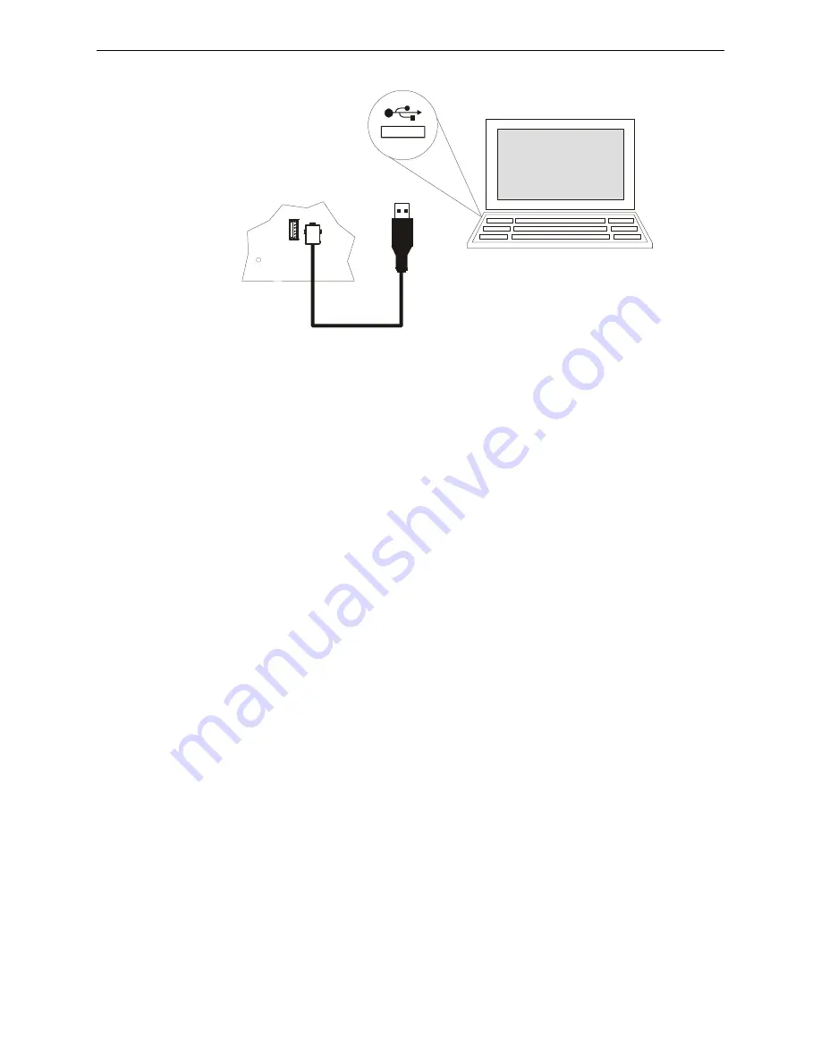
Connect the PC to the panel using a standard Male A to Male B USB cable.
2.
Run the VL software.
3.
Assure that the USB icon in the VL application window is
green
. If the icon is
black
then the
VL software has not established communication with the panel. Recheck the USB cable
connection. If the USB icon turns
red
while using the VL, then the VL has determined that the
USB connection has become “disconnected”.
Writing a Message to the Panel
1.
From the “Source/Destination Message” drop-down box select any one of the message slot
locations “Message 01" through “Message 14".
2.
From the “File Select” browse button search for and select the desired message (in .ske format)
stored on the PC to be written to the panel.
3.
Select “Write File To Panel” in the application window.
4.
Answer “Yes” in the “Confirm Write” box that appears.
5.
Repeat steps 1 through 4 for any addition messages to be written, or close VL software if
finished.
Reading a Message from the Panel
1.
From the “Source/Destination Message” drop-down box select any one of the message slot
locations “Message 01" through “Message 14".
2.
In the “File Select” box specify the directory and filename (type in or use browse button) in
which to store the desired message from the panel to the PC. Filenames should have a .ske
extension. Provide a unique filename as needed to avoid overwriting existing message files.
3.
Select “Read File From Panel” in the application window.
The VL will alert the user if there is
no message stored (blank) in the selected message slot location
.
4.
Repeat steps 1 through 3 for any addition messages to be read, or close VL software if finished.
Moving a Message to a Different Slot
To move a message from one message slot location to another - first read the desired message from
its current message location into the PC, and then write this message file from the PC to the new
message slot location. Follow steps 1 through 3 in "Reading a Message from the Panel" above to
read the message and steps 1 through 4 in "Writing a Message to the Panel" to write the message.
3.5 Programmed Activation by FACP
The table below defines the capabilities for the FireLite FACPs that can automatically trigger the
audio system using the audio system’s “FACP Data Bus”. The FACP annunciator bus serves as
“FACP Data Bus” to the audio system. Note that automatic triggering capability is dependent upon
the FACP model, FACP version, and which annunciator bus protocol is used.
us
bc
on
n.
w
m
f
Содержание ECC-100
Страница 102: ...102 Emergency Command Center Manual P N LS10001 000FL E D 9 3 2014 Slide in Labels...
Страница 104: ...104 Emergency Command Center Manual P N LS10001 000FL E D 9 3 2014 Slide in Labels...
Страница 110: ...Cut along dotted line...
Страница 112: ...World Headquarters 1 Firelite Place Northford CT 06472 1653 USA 203 484 7161 fax 203 484 7118 www firelite com...


