

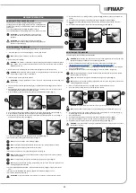
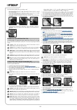

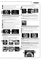
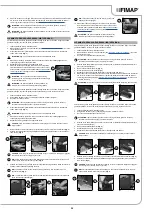


The solution tank can be filled with water in three different ways:
•
Removing the cap/measuring device (3) (
Fig. 3
) and filling the solution tank by means of a rubber
tube or a bucket (
Fig. 4
).
•
Using the filler tube (4) (
Fig. 5
), which supports the water tube on its own. In this case, remember
to remove the cap/measuring device (3) to ensure the air is properly vented.
•
Using the optional system for automatic clean water top-up. This system has a float for avoiding
any overflow.
DETERGENT SOLUTION (VERSIONS WITHOUT FSS)
After filling the solution tank with clean water add the liquid detergent to the tank in the concentration
and manner indicated on the detergent manufacturer's label. To prevent the formation of an excessive
amount of foam that could damage the vacuum motor, use the minimum percentage of detergent
required.
CAUTION
: protective gloves should always be worn before handling detergents or acidic or
alkaline solutions, to avoid serious injury to the hands.
CAUTION
: always use detergents whose manufacturer's label indicates their suitability for
scrubbing machines. Do not use acid or alkaline products or solvents without this indication.
ATTENTION
: acid or alkaline maintenance detergents can be used, as long as they have pH
values between 4 and 10, and do not contain: oxidising agents, chlorine or bromine,
formaldehyde, mineral solvents. The detergents used must be suitable for use with scrubbing
machines.
CAUTION
: always use low-foam detergent. To avoid the production of foam, put a minimum
quantity of anti foam liquid in the recovery tank before starting to clean. Do not use pure acids.
NB
: to make it easier to measure the detergent on the cap/measuring device, there are notches
indicating the detergent percentage quantities that can be used. The notches range from a
minimum of 0.1% to a maximum of 0.5%.
5. Fill with clean water, at a temperature no higher than 50°C and no lower than 0°C. The amount
inside the tank can be seen by means of the level tube (5) (
Fig. 6
) on the rear left-hand side of
the machine.
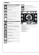
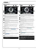
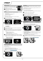
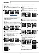
FILLING THE DETERGENT CANISTER (VERSIONS WITH FSS)
After filling the solution tank with clean water, you must fill the detergent canister. Before filling the
canister, carry out the following steps:
1.
Take the machine to the usual place for filling the solution tank.
2. Make sure the machine is in a safe condition (see “
”).
3. Grip the handle (1) on the right-hand side of the recovery tank (
Fig. 1
) and turn the tank as far as
it will go, until it reaches the maintenance position.
4. Disconnect the male insert (2) from the female insert (3) on the cap (4) of the detergent canister
(5) (
Fig. 2
).
ATTENTION
: before pulling on the male insert, push the lever on the female insert.
5. Grip the handle (6) on the detergent canister (5) to remove it from the compartment in the solution
tank (
Fig. 3
).
6. Remove the cap (4) from the detergent canister (
Fig. 4
).
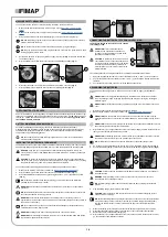
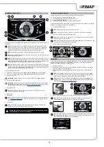
7. Fill the canister with the required detergent, as indicated on the label supplied with the machine.
CAUTION
: protective gloves should always be worn before handling detergents or acidic or
alkaline solutions, to avoid serious injury to the hands.
WARNING
: always use low-foam detergent. To avoid the production of foam, put a minimum
quantity of anti foam liquid in the recovery tank before starting to clean. Do not use pure acids.
WARNING
: always use detergents whose manufacturer's label indicates their suitability for
scrubbing machines. Do not use acid or alkaline products or solvents without this indication.
ATTENTION
: the dosing system is suitable for frequent maintenance cleaning. acid or alkaline
maintenance detergents can be used, as long as they have pH values between 4 and 10, and
do not contain: oxidising agents, chlorine or bromine, formaldehyde, mineral solvents. The
detergents used must be suitable for use with scrubbing machines. Wash the circuit with water
after use if the system is not used daily. The system can be excluded. In case of sporadic use of
detergents with pH between 1-3 or 11-14, use the floor scrubbing machine in the traditional way
by adding the detergent in the clean water tank and excluding the dosing circuit.
8. Make sure you tighten the cap (4) properly to avoid any leakage of liquid while working. Make
sure the detergent suction filter (7) is correctly positioned on the bottom of the canister (
Fig. 5
).
9. Grip the canister handle (6) to replace the canister (5) in its compartment inside the solution tank.
10. Connect the male insert (2) to the female insert (3) in the cap (4) of the detergent canister (5).
11. Grip the handle (1) on the right-hand side of the recovery tank and turn the tank as far as it will go,
until it reaches the work position.
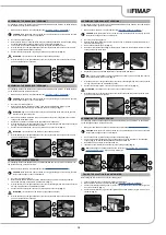
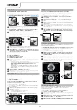
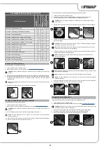
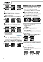
Before beginning to work, it is necessary to:
1. Make sure the recovery tank is empty. If it isn't, empty it (see “
2.
Check that the amount of detergent solution in the solution tank is sufficient for the type of work
to be performed. If it isn't, top up the solution tank (see “
FILLING THE SOLUTION TANK WITH
”). Check the level tube (1) in the rear left-hand part of
the machine (
Fig. 1
).
3. Check the rubber squeegee blades are in good working condition. If they aren't, replace them
(see “
REPLACING THE SQUEEGEE BODY RUBBER BLADES
4.
Check the brush is in good working condition. If it isn't, replace it (see “REPLACING THE BRUSH
5.
Check the machine is switched off. If it isn't, turn the main switch (2) to “0” by rotating the key a
quarter turn in the direction of the arrow (
Fig. 2
). Remove the key from the instrument panel.
6. Grip the handle (3) on the right-hand side of the recovery tank (
Fig. 3
) and turn the tank as far as
it will go, until it reaches the maintenance position.
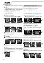
PREPARING TO WORK
7. Connect the main system connector (4) to the battery connector (5) (
Fig. 4
).
ATTENTION
: this process must be carried out by qualified personnel.
8. Grip the handle (3) on the right-hand side of the recovery tank and turn the tank until it reaches
the work position.
9. Make sure the electronic brake is engaged. If it isn't, turn the lever (6) in the direction of the
arrow. The traction gearmotor is located on the rear right-hand side of the machine (
Fig. 5
).
10.
Check the water tap is fully open - the water adjustment knob (7) must be turned fully in the
direction shown by the arrow (
Fig. 6
).
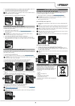
11. Make sure the solution tank drainage cap (8) is closed. If it isn't, close it (
Fig. 7
).
12.
Make sure the water filter cap (9) is closed. If it isn't, close it (
Fig. 8
).
13. Make sure the cap of the recovery tank drainage tube (10) is closed. If it isn't, close it (
Fig. 9
).
14. Make sure the vacuum tube (11) is correctly connected to the sleeve in the squeegee body. If it
isn't, connect it (
Fig. 10
).
15.
Make sure the vacuum motor filter (12) is correctly connected and is clean (
Fig. 11
). If it isn't,
clean it (see “
CLEANING THE RECOVERY TANK FILTERS
”).
16.
Make sure the filter basin (13) is correctly connected and is clean (
Fig. 12
). If it isn't, clean it (see
CLEANING THE RECOVERY TANK FILTERS
”).
17. Make sure the recovery tank cover is properly closed. If it isn't, close it.
16
4
3
5
3
4
6
5
2
3
1
1
2
6
4
3
5
5
4
4
7
1
1
2
2
3
3
5
6
6
7
4
4
5
8
9
7
8
9
10
Содержание MAXIMA 2017 PLUS
Страница 2: ......
Страница 36: ...36 NOTE ...
Страница 37: ...37 NOTE ...
Страница 38: ...38 NOTE ...
Страница 39: ......


