FIKE CORPORATION
SERVICING
UL S2203
SHP Product Manual
Page 35 of 43
FM 0Z8A0.AY
Manual P/N: 06-130
Rev. No: 3, 04/02
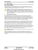
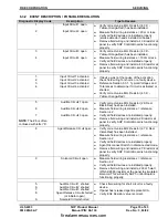
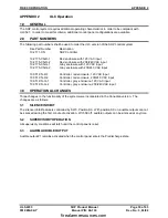
6.3.2 EVENT DESCRIPTION / POSSIBLE RESOLUTION
Diagnostic Display Code
Description
Tips to Resolve
1
2
Input Circuit 1 open
Input Circuit 2 open
♦
Verify correct value EOL Resistor (4.3 K -
Yellow-Orange-Red) has been installed.
♦
Measure field wiring resistance = 20
Ω
or less.
♦
Verify all field devices are installed properly
(smoke detector heads installed on bases).
♦
Remove field wiring and install a 4.3K resistor at
panel to verify SHP Control Board is functioning
properly.
3
4
Input Circuit 3 open
Input Circuit 4 open
♦
Verify correct value EOL Resistor (4.3K -
Yellow-Orange-Red) has been installed.
♦
Measure field wiring resistance = 100
Ω
or less.
♦
Verify all field devices are installed properly.
♦
Remove field wiring and install a 4.3K resistor at
panel to verify SHP Control Board is functioning
properly.
1.
2.
3.
4.
Input Circuit 1 activated
Input Circuit 2 activated
Input Circuit 3 activated
Input Circuit 4 activated
♦
If device was not the cause of the activation
check field wiring for shorts, or a faulty device.
♦
Reference Section 6.3.1, Typical Voltages and
Tolerances to determine if circuit is activated or
shorted.
♦
Verify correct value EOL Resistor (4.3 K -
Yellow-Orange-Red)
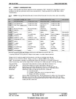
5
6
7
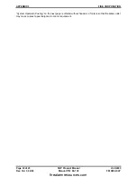
NOTE
: The # 6 is often
confused with letter “b”.
Audible Circuit 1 open
Audible Circuit 2 open
Audible Circuit 3 open
♦
Verify correct value EOL Resistor (2 K Red-
Black-Red) has been installed.
♦
Measure field wiring resistance = reference
Section 4.2
♦
Verify all field devices are installed properly.
♦
Remove field wiring and install a 2K resistor at
panel to verify SHP Control Board is functioning
properly.
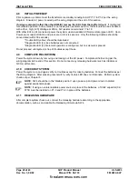
8
Agent Release Circuit open
♦
Verify correct value EOL Resistor (2.7 K Red-
Violet-Red) has been installed.
♦
Measure field wiring resistance = reference
Section 4.2
♦
Verify all field devices are installed properly.
♦
Agent Disconnect Switch in disconnected mode.
♦
Remove field wiring and install a 2.7K resistor at
panel to verify SHP Control Board is functioning
properly.
9
Solenoid Circuit open
♦
Measure field wiring resistance = reference
Section 4.2
♦
Verify all field devices are installed properly.
♦
Remove field wiring and install a 200
Ω
5 watt
(P/N 02-2686) resistor at the panel to simulate a
solenoid. This will verify SHP Control Board is
functioning properly.
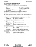
5.
6.
7.
8.
9.
Audible Circuit 1 shorted
Audible Circuit 2 shorted
Audible Circuit 3 shorted
Agent Release Circuit shorted
(or initiator open)
Solenoid Circuit shorted
♦
Check field wiring for short circuit or a faulty
device.
♦
If panel has released agent replace GCA.
♦
Verify EOL Resistor value is correct.
firealarmresources.com
Содержание SHP 10-051
Страница 2: ...firealarmresources com ...
Страница 4: ...firealarmresources com ...
Страница 48: ...firealarmresources com ...
Страница 50: ...firealarmresources com ...
Страница 51: ...firealarmresources com ...

