


page 10 of 16
INSTALLATION: WIRING & CONTROLS
The fi nal step in this fan’s installation is to install its controls. The standard control package included with this
fan contains: the control box; 1 hardwired wall switch; 1 mounting bracket for the wired switch and 50 ft. of
orange CAT5 cable.
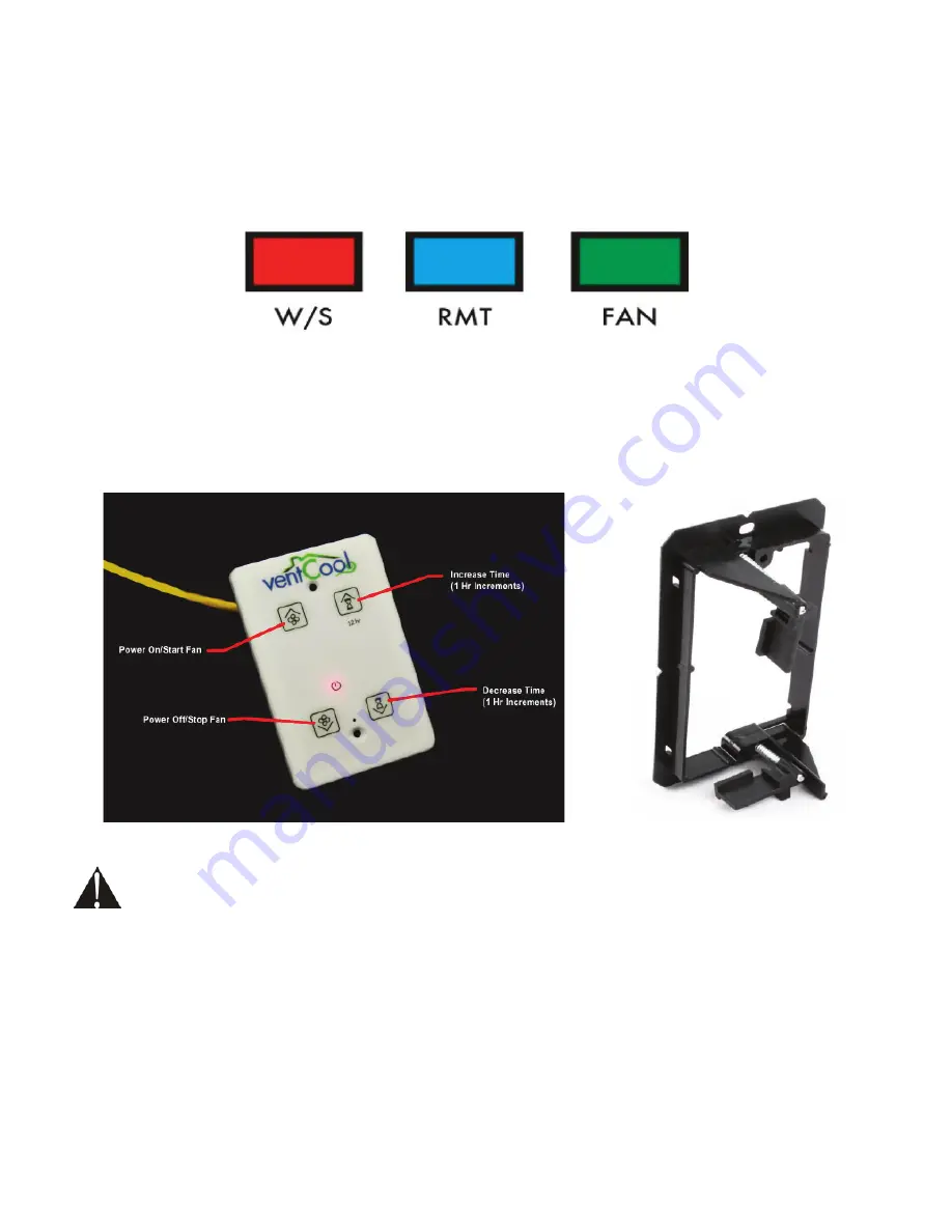
First, locate the control box attached to fan assembly section.. The control box is an 12.375” x 5.5” x 2” galvanized
steel electrical box with a series of 3 RJ45 ports on one side. Refer to Figure 12. These ports are labeled with
the following label:
Connect the orange CAT5 cable to the red W/S
W/S port located on the electrical control box on the fan housing. Then,
run the cable through the attic and down the wall to the desired location for the hardwired wall switch. Refer to
Figure 13 for Wall Switch. Note: This cable is low-voltage but unshielded. Building Codes require unshielded
Note: This cable is low-voltage but unshielded. Building Codes require unshielded
low-voltage wiring to be run through shielded conduit. Do not run cable in parallel with 110V or greater wiring.
low-voltage wiring to be run through shielded conduit. Do not run cable in parallel with 110V or greater wiring.
Connect the included hardwired switch to the fan’s control box regardless of whether or not it will be
installed in a wall.
Because an accessible hardwired switch is necessary for providing technical
Because an accessible hardwired switch is necessary for providing technical
support, this switch MUST be installed.
support, this switch MUST be installed. FAILURE TO INSTALL THE HARDWIRED WALL SWITCH WILL VOID
FAILURE TO INSTALL THE HARDWIRED WALL SWITCH WILL VOID
THIS FAN’S WARRANTY!
THIS FAN’S WARRANTY!
FIGURE 12: RJ45 Port Labels on Electrical Control Box
Using the provided wall mounting bracket (Figure 14) as a template, trace an outline on the wall where you would
like the switch to be located. Following this outline, cut a hole for the mounting bracket, place it inside, and secure
it with the locking tabs by tightening the silver screws. Then, connect the free end of the red CAT5 cable
to the port on the back of the wall switch. Set the switch in place and secure its face plate to the mounting
bracket using the attached white screws.
The wall switch is confi gurable for multiple VentCool product lines which means it can be confi gured to
operate in different modes. Refer to Figure 15 when setting DIP switches for VentCool 3.4 and 4.9
operating parameters. Verify the wall switch control panel DIP switches are set to switch 1 is ON and 2
Verify the wall switch control panel DIP switches are set to switch 1 is ON and 2
thru 4 are OFF.
thru 4 are OFF. This setting will allow the wall switch to operate as a ten speed, 12 Hr timer confi guration.
CAUTION: Failure to properly set wall switch confi guration will cause the VentCool WHF system to not work.
CAUTION: Failure to properly set wall switch confi guration will cause the VentCool WHF system to not work.
FIGURE 13: Wall Switch
FIGURE 14: Wall Bracket
WALL SWITCH INSTALLATION
(Refer to Figure 12 for Electrical Control Box Port Labeling)
P/N 780100500 05/19 Rev B


