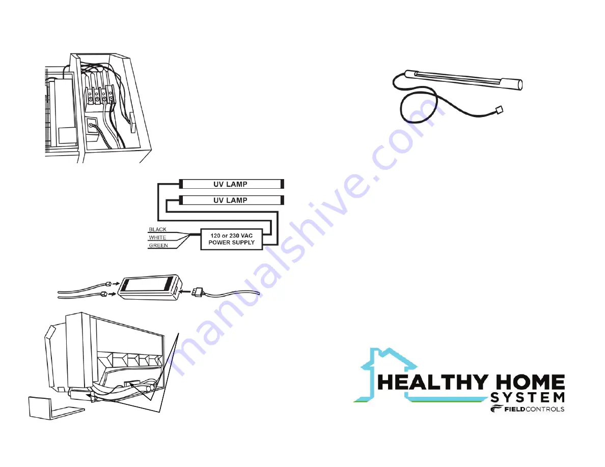
Power Supply Installation
1. Remove the control box cover and connect the wiring harness as shown.
NOTE:
Some indoor systems
may require additional wiring
to provide line voltage to the
MiniSplit UV™ power supply.
2. Wiring Diagram
3. Insert the UV lamp cable connectors and wiring
harness connector into the power supply.
Model: UV-30DL ballast wiring
•Black to hot terminal
•White to neutral
•Green to ground
Model: UV-30DL ballast wiring
•Black to line 1
•White to line 2
•Green to ground
Lamp Replacement
The UV-30DL UVC lamp is to be replaced annually for optimum perfor-
mance. Germicidal effectiveness falls off over time so uvc lamp replacement
is necessary even if the lamps continue to emit visible light after one year.
Replacement lamp only with Part No. 602610100
Model DL-30LAMP
NOTE:
Use of replacement UVC lamps other than Field Controls Healthy
Home System specified replacement part number will void warranty.
CAUTION:
UVC lamps contain small amounts of mercury. Dispose of lamps
in accordance with local environmental regulations.
Visit www.earth911.com and www.lamprecycle.org for more information.
4.Tuck the power supply into the
line chase on the back of the
AC unit or place it in or under
the control box or other secure
location.
5.Return power to the system
and confirm that UV-30DL is
working.
6.Apply the UV warning sticker
in an appropriate location.
NOTE:
It can take up to 10 minutes for the
UV lamp to warm up and fully illuminate.
POWER LEAD
LAMP CABLES
This Instruction Manual may be downloaded and printed from the
Field Controls website (www.fi eldcontrols.com)
WARRANTY
For complete warranty details about this product or any Field
Controls product, visit: www.fi eldcontrols.com/warranty
Field Controls Technical Support
1.800.742.8368
fi eldtec@fi eldcontrols.com
www.fi eldcontrols.com
252.522.3031 sales@fi eldcontrols.com
P/N 780109300 RevA


