background image

Step 6 

(continued)

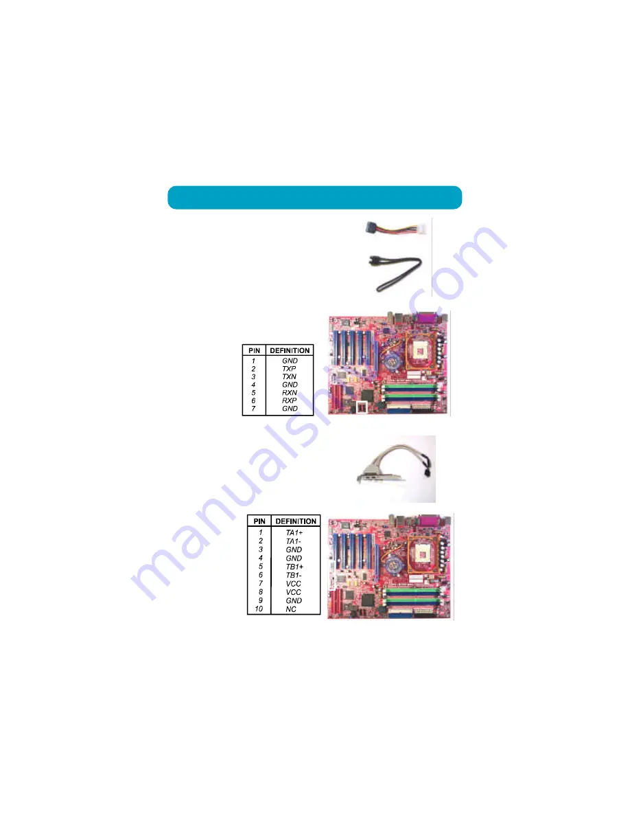
1394

Please use the optional 1394 cable
to install the 1394 connection.

The pin definitions
of the pinheaders
(positions in the
white rectangle in
the right figure)
are shown in the
right table:

Serial ATA

Use  the optional  SATA cable to
connect to the hard drives (lower
one is a SATA data cable) and link
with the power supply (upper one
is a SATA power cable).

The pin definitions of the SATA
pinheaders (positions in the white
rectangle in the right figure)
are shown in the
right table:

Содержание P4-875P MAX

Страница 1: ...875 Dynasty MAINBOARD MANUAL DOC No M03207 Rev A2 Date 6 2003 Part No 25 11242 02 P4 875P MAX ...

Страница 2: ...uter components Wear a static wrist strap which fits around your wrist and is connected to a natural earth ground Touch a grounded or anti static surface or a metal fixture such as a water pipe Avoid contacting the components on add on cards motherboards and modules with the golden fingers connectors plugged into the expansion slot It is best to handle system components by their mounting brackets ...

Страница 3: ...l the CPU 2 5 ConnectATX Power 2 6 4 Install Expansion Cards 2 7 5 ConnectDevices 2 9 FloppyDisketteDrive Connector 2 9 IDEDevice Connectors 2 9 Fan Connectors 2 10 Power Connectors 2 11 System Chassis Open Alarm Connector 2 11 SPDIF Out Connector 2 12 Debug LEDDisplay Connector 2 12 Front Panel Block Power LED IR and Speaker Connector 2 13 Serial ATA Connectors 2 14 CDAudio In Connector 2 15 1394...

Страница 4: ...ipherals 3 10 Power Management Setup 3 14 PnP PCI Configurations 3 18 PC Health Status 3 19 Frequency Voltage Control 3 20 Load Fail SafeDefaults 3 21 Load OptimizedDefaults 3 21 Supervisor User Password 3 21 Save and Exit Setup 3 22 Exit without Saving 3 22 Audio I O Jacks 2 18 Front Audio Connector 2 18 5 1Audio Channel Feature 2 19 Universal Serial Bus Connectors 2 20 ...

Страница 5: ...m It completely software compatible with parallel ATA requiring no mofication to your operating sys tem Two types of RAIDconnections are provided IDE HPT 372 and SATA Intel ICH5R The onboard serial ATA feature includes RAID function to provide you with a more efficient storage backup For more detail please read the help file in the lst Utilities CD The 1stMainboard comes with a versatile range of ...

Страница 6: ...ppears in your monitor Please select Auto Installation It will auto matically detect which software tools patch files drivers that the mainboard needs Press OK button to go through the whole instal lation procedure in a very straight forward and easy way It also provides you with a custom way to select wanted patch files and software drivers that for onboard chips use The top menu of lst Utilities...

Страница 7: ...1 3 Overview P4 875P MAX ...

Страница 8: ...Memory 4 memory sockets support 184 pinDDR 333 400 memory size totally upto 4GBz The combinations of FSB DDR must followed FSB DDR 800 400 800 333 533 333 ExpansionSlots 1AGPSlot support 3 0 4X 8X 0 8V 1 5V 5 PCI Slots IDEConnections 2 IDE connectors PIO mode UltraDMA66 100 up to 4 devices SATAConnections 2 ports controlled by embeded ICH5R SATA function level 0 1 RAID functions not tested yet ...

Страница 9: ...0 100 Ethernet orGiga LAN IEEE1394Ports Agere FW323 2 ports 1 bracket with cable MountingHoles 9 holes MainboardSize 12 x 9 6 unit inch AudioFeatures RealtekALC650 controller AC97 2 2 compliant LINE_IN LINE_OUT MICROPHONE_INJack 5 1 audio channel A73 audio bracket with cable optional front audio pinheaders RAID IDE Connections 2 ports controlled by HighPoint 372 RAID function Level0 1 0 1 up to 4 ...

Страница 10: ...rt LogoGenie A user friendly GUI supporting Windows 95 98SE not Windows 2000 NT ME XP LogoGenie allows you to customize create or select a Logo which will be displayed when the system is booting NOTE Please read Page 3 7 for detail information Easy Key Instead of completing the multi layered BIOS setup process these 3 Easy Key functions provide direct access to Sub Menu when completing BIOS settin...

Страница 11: ...tall supporting software tools WARNING Excessive torque may damage the mainboard When using an electric screwdriver on the mainboard make sure that the torque is set to the allowable range of 5 0 8 0kg cm Mainboard components contain very delicate Integrated Circuit IC chips To prevent static electricity from harming any of the sensitive components you should follow the following precau tions when...

Страница 12: ... 1 2 to disable the effect of CMOS clearance 5 connect the ATX power cable close the system case 6 turn on your computer until CMOS checksum error appears 7 hold down the Delete key when boots 8 enter the BIOS Setup to re enter user preferences 1 Set System Jumpers Jumpers are used to select the operation modes for your system Some jump ers on the board have three metal pins with each pin represen...

Страница 13: ...2 3 Installation Procedures BIOS Protect The jumper helps users to prevent the 64K boot block table area in the BIOS ROM from being overwritten by mistake ...

Страница 14: ...clip on both ends of the socket will close up to hold the DDRDIMM in place when theDDR DIMM reaches the socket bottom NOTE 1 To enable dual channel it must be same density 128 256MB etc same technology 128 256Mb etc same bus width x8 x16 both single or dual sided installed on symmetical memory slots 2 If your system uses an 800MHz CPU with DDR333 memory the memory interface of the chipset will run...

Страница 15: ... a fan with heatsink that approved by CPU manufacturer to avoid CPU damage For detail information please refer to the CPU manufacturer website The mainboard has built in Switching Voltage Regulator to support CPU Vcore autodetection That is It has the ability to detect and recognize the CPU volt age clock ratio and enables users to set up the CPU frequency from the BIOS Setup Screen Users can adju...

Страница 16: ...module Affix the CPU by pressing the lever downward and locking it beside the socket Connect ATX Power The 20 hole power plug top right is connected to the ATX power 20 pin pinheaders The 4 hole 12V power plug bottom right is inserted in the ATX_12V power connector The plug from the power supply will only insert in one orientation because of the different hole sizes Find the proper orientation and...

Страница 17: ...w to connect an expansion card to one of your system expansion slots Expansion cards are printed circuit boards that when connected to the mainboard increase the capabilities of your system For example expansion cards can provide video and sound capabilities The mainboard features one AGP and three PCI bus expansion slots NOTE Users The CPU installing procedures should be 1 Insert the CPU with its...

Страница 18: ...crew that secures the slot cover and pull the slot cover out from the computer chassis Keep the slot cover mounting screw nearby 3 Push the card firmly into the slot Push down on one end of the expan sion card then the other Use this rock ing motion until them card is firmly seated inside the expansion slot Se cure the card with the screw removed in Step 2 ...

Страница 19: ... the floppy ribbon cable below onto the floppy connector The colored stripe indicated by the arrow head right of the ribbon cable must be the same side with the Pin 1 IDE Device Connectors The two connectors PRIMARYand SEC ONDARY are used for your IDE hard disk drives CD drives LS 120 drives or IDE ZIP drives The red stripe of the ribbon cable must be the same side with the Pin 1 The two connector...

Страница 20: ...level Save and exit Reboot the system Be gin to install the operating system and drives If install Windows 2000 NT XP on a hard disk that connect to IDE3 or IDE4 connector 1 Copy all files in the subdirectory RAID HighPoint to floppy disk on another computer For example If driver CD is D drive and the floppy drive is A Execute Windows Explorer Select All Send to A or go to DOS prompt D RAID HighPo...

Страница 21: ... from the power supply will only insert in one orientation because of the different hole sizes Find the proper orientation and push down firmly making sure that the pins are aligned System Chassis Open Alarm Connector The 2 pin male connector allows you to enable or disable system activation if and when the system out casing is being removed A high level signal to the connector will indicate to th...

Страница 22: ...r orientation of SPDIF connection may cause damage of your device The above is an 80 Port Debug 7 segment LED display Please read the last two pages about the display meanings Debug LED Display Connector The mainboard has one optional debug LED display feature one is an 80 Port Debug 7 segment LED display the other is a pinheader for its display device ...

Страница 23: ...em by yourself The plug wires polari ties of these buttons will not affect the function 1 Reset Switch is connected to the reset button Push this switch to reboot the system instead of turning the power button off and on 2 HDD LED is connected to the IDE device indicator This LED will blink when the hard disk drives are activated NOTE Users that want to use IR port must adjust BIOS feature to acti...

Страница 24: ...le pin assignments of SATA connector NOTE Please read BIOS Setup Integrated Peripherals the fea tures about SATA setting for more information about the usage of the feature Speaker is connected with the case speaker IR is a pinheader that is used for linking with your IDdevice to allow transmis sion of data to another system that also supports the IR feature This mainboard provides users with two ...

Страница 25: ...des you with two connec tions with the peripherals which own 1394 connectors by an optional bracket with cable see the figure below The pin definitions of the 1394 pinheaders are listed below also CD Audio In Connectors The connectors CD_IN and AUX_IN are for CD ROM drive audio analog input use ...

Страница 26: ...AN Connector The LAN RJ45 port jack is used for the LAN cable plug PS 2 Keyboard and Mouse Connector These two 6 pin female PS 2 keyboard is purple color and PS 2 mouse is green color connectors are used for your PS 2 keyboard and PS 2 mouse ...

Страница 27: ... COM1 2 9 pin D sub male connector with teal color allow you to connect with your devices that use serial ports such as a serial mouse or an external modem Printer Connector This 25 pin D Sub female burgundy colored connector is attached to your printer ...

Страница 28: ...pec It allows users to attach the audio device via front panel instead of rear panel by a ribbon cable that in some cases Its pin definitions are resented below Audio I O Jacks LINE_OUT lime can be connected to headphones or preferably powered speakers LINE_IN light blue allows tape players or other audio sources to be recorded by your computer or played through the LINE_OUT MIC_IN pink allows mic...

Страница 29: ...nnel audio output with its software tool The 5_1_AUDIO sound feature are offered via the pinheaders with an optional A73 bracket with ribbon cable The pinheaders pin assignments are shown below left 5 1 Audio Channel Feature When use the daughter board plug in the LINE_OUT jack for the front speaker audio output right and left ...

Страница 30: ... mainbaord have eight USB ports four USB black jacks that integrated on the edge of the board the other four USB ports on the board They allows uses to attach with USB devices either from rear or front panels The USB cabe that comes with your mainboard is used to connecting between the USB pinheaders and rear panel See the photo below ...

Страница 31: ...ion error and asks the user to run the Setup program Use the arrow keys to select and press Enter to run the selected program The mainboard comes with the chip that Award BIOS that contains the ROM Setup information of your system This chip serves as an interface between the processor and the rest of the mainboard components This section ex plains the information contained in the Setup program and...

Страница 32: ...necessary Use the arrow keys to highlight the item and then use PgUp or PgDn keys to select the value you want in each item Date To set the date highlight the Date field and then press Page Up PageDown or keys to set the current date Follow the month day and year format Time To set the time highlight the Time field and then press Page Up PageDown or keys to set the current time Follow the hour min...

Страница 33: ...h the disk drive changes the write current LandingZone The cylinder number that the disk drive heads read write are seated when the disk drive is parked Sector The sector number of each track defined on the hard disk Drive A Drive B This field records the types of floppy drives installed in the system To enter the configuration value for a particular drive highlight its corre s pondi n gf i e l da...

Страница 34: ... The options are Enabled Disabled Hyper Threading Technology appeared if your CPU supports it When enabled it performs as Hyper Threading tech does if the CPU sup port it The options are Enabled Disabled Quick Power On Self Test When enabled allows the BIOS to bypass the extensive memory test The options are Enabled Disabled Advanced BIOS Features Hard Disk Boot Priority This feature will auto det...

Страница 35: ...BIOS to automatically enable the Num Lock Function when the system boots up The options are On Off Gate A20 Option When set at Fast allows a faster access response under Protected mode The options are Fast Normal Typematic Rate Setting The term typematic means that when a keyboard key is held down the character is repeatedly entered until the key is released The options are Disabled Enabled Typema...

Страница 36: ...o select MPS Multi Processor Spec version control for OS when logo test executes The options are 1 1 1 4 OS Select For DRAM 64MB If your operating system OS is OS 2 select the option OS2 Otherwise stay with the default setting Non OS2 The options are Non OS2 OS2 HDD S M A R T Capability S M A R T stands for Self Monitoring and Analysis Reporting Technol ogy which allows your hard disk drive to rep...

Страница 37: ...ash BIOS Restart the system after complete it 8 POST screen holds A message about BIOS Guardian shows 9 Press Gkey The feature BIOSGuardian will be enabled again Full Screen LOGO Show It decides whether or not the full screen logo is shown during system booting up The options are Enabled Disabled NOTE 1 LogoGenie supports Award BIOS only 2 If you create a Logo file bmp by LogoGenie the file size m...

Страница 38: ... 2 5 3 Active to Precharge Delay This feature allows user to set Active to Precharge Delay if any SDRAM installed The options are 8 7 6 5 DRAM RAS to CAS Delay The feature allows user to set the delay time that from the DRAM RAS active to CAS The options are 4 3 2 DRAM RAS Precharge The feature allows user to set the DRAM RAS Precharge Time The options are 4 3 2 Memory Frequency For This feature a...

Страница 39: ...128 256 Init Display First When you install an AGP VGA card and a PCI VGAcard on the board this feature allows you to select the first initiation of the monitor display from which card The options are PCI Slot AGP System BIOS Cacheable SettingatEnabledwillallowthecachingoftheBIOSROMF0000H FFFFFH resulting in better system performance It may cause system error when some programd try to access the m...

Страница 40: ...abled On Chip Primary PCI IDE When enabled it allows you to use the onboard primary PCI IDE The options are Enabled Disabled IDE Primary Master Slave PIO Allows an automatic or a manual configuration of the PCI primary IDE hard drive master slave mode The options are Auto Mode 0 Mode 1 Mode 2 Mode 3 Mode 4 IDE Primary Master Slave UDMA Allows an automatic configuration of the PCI primary IDE hard ...

Страница 41: ...ure allows users to select SATAspecifications that embeded func tions in South Bridge The options are IDE RAID On Chip SerialATA This feature allows users to select the SATAfunction modes that embeded in South Bridge Setting at Disabled will disable STAT controller Set at Auto will allow the BIOS to arrange it Setting Combined Mode will make PATAand SATAcombined Max of 2 IDE drives in each channel...

Страница 42: ... The options are Disabled Enabled USB Mouse Support If USB mouse is installed please set at Enabled The options are Disabled Enabled AC97Audio This feature auto detects if you use a card that with a CODEC to enable or disable the AC97 audio function The options are Auto Disabled Onboard 1394 Chip This feature allows you to disable the onboard 1394 feature The options are Enabled Disabled Onboard R...

Страница 43: ...s of the system when the system power is resumed The options are Former Sts On Off UART Mode Select Allows you to select the IR modes if the serial port 2 is used as an IR port Set at Standard if you use COM2 as the serial port as the serial port instead as an IR port The options are Normal IrDA ASKIR SCR ECP Mode Use DMA This feature allows you to select Direct Memory Access DMA channel The optio...

Страница 44: ...me This feature allows you to decide the way if VGA BIOS should be called when the system resumes from S3 state if the above feature is set at S3 PTR or S1 S3 The options are Auto Yes No Select User Define for configuring your own power management features Min Saving initiates all predefined timers in their minimum values Max Saving on the other hand initiates maximum values The options are User D...

Страница 45: ... Suspend mode The options are Disable 1 2 4 8 10 20 30 40 Min 1 Hour Suspend Type The option allows you to select VGA status when the system goes to suspend mode The options are Stop Grant PwrOn Suspend MODEM Use IRQ This feature allows you to select the IRQ to meet your modem IRQ The options are NA 3 4 5 7 9 10 11 Soft Off byPWR BTTN The selectionDelay 4 Sec will allow the system shut down after ...

Страница 46: ...the suspend mode The options are Disabled Enabled Wake Up by PCI card When set at Enabled any PCI PM event awakes the system from a PCI PM controlled state The options are Disabled Enabled Power On by Ring An incoming call via modem awakes the system from its soft off mode The options are Disabled Enabled Resume by Alarm This feature allows you to set the when the system being turned on from the s...

Страница 47: ...system timer will be reloaded and the system will not be into the suspend mode The options are Disabled Enabled Secondary IDE 1 When the secondar slave HDD is working the system timer will be re loaded and the system will not be into the suspend mode The options are Disabled Enabled FDD COM LPT Port When FDD COM or LPT is working the system timer will be reloaded and the system will not be into th...

Страница 48: ...al If the manual options after the featrue IRQ Resources being pressed of IRQ Assigned To are PCI Device Reserved When resources were con trolled manually assign each system interrupt a type depending on each device type to use the interrupt Reset ConfigurationData Enabling it to reset the systemExtended SystemConfigurationData ESCD when you exit Setup if you have installed a new add on card and t...

Страница 49: ... 8 Assignment This feature allows you to assign the PCI IRQ numbers for PCI slots Selecting the default Auto allows the PCI controller to automatically allo cate the IRQ numbers The options are Auto 3 4 5 7 9 10 11 12 14 15 PC Health Status ShutdownTemperature This feature helps to shutdown the system when the system temperature is as high as the selected temperature to prevent from the overheat p...

Страница 50: ...ws you to select the combination of asynchronous AGP PCI clock The options are Auto 66 33 MHz 73 36 MHz 80 40 MHz Auto Detect PCI Clk When enabled BIOS will detect the PCI slot slot If no any device in BIOS will auto disable its clock The options are Enabled Disabled Spread Spectrum This feature allows users to select the range of spread spectrum The options are Disabled 0 35 0 50 0 75 1 00 NOTE I...

Страница 51: ...imal performance This submenu is selected for default settings which provide the best system performance Supervisor User Password To enable the Supervisor User passwords select the item from the Standard CMOS Setup You will be prompted to create your own password Type your password up to eight characters and press Enter You will be asked to confirm the password Type the password again and press En...

Страница 52: ...nge anything press Esc again or move cursor to Exit Without Saving and press Y to retain the Setup settings The following message will appear at the center of the screen to allow you to save data to CMOS and exit the setup utility SAVE to CMOS and EXIT Y N Under the BIOS Feature Setup if Setup is selected under the Security Option field and the Supervisor User Password is enabled you will be promp...

Страница 53: ...875 Dynasty Pentium 4 with Part Number 25 11242 41 ...

Страница 54: ...EZ Guide Intel 875 Series ynasty entium 4 with NOTE The information in this document are subject to change without fur ther notice ...

Страница 55: ...batteries according to the manufacturer s instructions 4 Never run the processor without the heatsink properly and firmly attached PERMANENT DAMAGE WILL RESULT 1 Install CPU 7 Set jumpers 2 Install memory module 8 Assembly case 3 Install mainboard 9 Link peripherals 4 Install devices 10 BIOS setup 5 Install add on card 11 Install Drivers 6 Cconnect cables Before Start Intallation Procedures þ Main...

Страница 56: ... lever downward and locking it beside the socket Apply some thermal materials such as paste or tape on the CPU top and install a fan with heatsink that approved by CPU manufacturer to avoid CPU damage For detail information please refer to the CPU manufacturer website 3 Place the fan with heatsink on the CPU top and press down two plastic clips to hook up with the holes on the retention module on ...

Страница 57: ...ill close up to hold the DDRDIMM in place when theDDR DIMM reaches the socket bottom Step 2 Install Memory Module NOTE 1 To enable dual channel it must be same density 128 256MB etc same technology 128 256Mb etc same bus width x8 x16 both single or dual sided installed on symmetical memory slots 2 If your system uses an 800MHz CPU with DDR333 memory the memory interface of the chipset will runs at...

Страница 58: ...e torque is set to the allowable range of 5 0 8 0kg cm 2 Be aware of the shape edges in the case while installing board 1 Locate mounting holes on the mainboard 2 Place the board over the frame inside the chassis Be sure that the board and frame are aligned 3 Affix the mainboard by copper columns Step 3 Install Mainboard ...

Страница 59: ...Note The chassis might not be the same as yours The specifica tion here is only for reference Generally most cases are simi lar Front and Rear Panel ...

Страница 60: ...ppy Drive 1 Locate floppy drive frame and storage on the chassis 2 Place the drive from the front panel side into the frame 3 Affix the drive on the frame by screws 4 Connect the floppy cable and power cable http www fic com tw ...

Страница 61: ...inued CD DVD Drive 1 Locate CD DVD drive frame and storage on the chassis 2 Place the drive from the front panel side into the frame 3 Affix the drive on the frame by screws 4 Connect the IDE cable and power cable ...

Страница 62: ...sk Drive 1 Locate hard drive frame and storage on the chassis 2 Place the hard disk drive from the rear of the frame as the arroaw head indciated 3 Affix the drive on the frame by screws 4 Connect the IDE cable and power cable ...

Страница 63: ...he card firmly into the slot Push down on one end of the expan sion card then the other Use this rock ing motion until them card is firmly seated inside the expansion slot Se cure the card with the screw removed in Step 2 Step 6 Connect Wires 5 1 Audio Channel Please use the optional cable and A73 braket with cable to install the 5 1 au dio channel feature The pin definitions of the 5 1audio chann...

Страница 64: ...igure are shown in the table below ATX Power The 20 hole power plug top right is connected to the ATX power 20 pin pinheaders The 4 hole 12V power plug is inserted in the ATX_12V power connector The plug from the power supply will only insert in one orientation be cause of the different hole sizes Find the proper orientation and push down firmly making sure that the pins are aligned ...

Страница 65: ...e rectangle in the right figure are shown in the right table Serial ATA Use the optional SATA cable to connect to the hard drives lower one is a SATA data cable and link with the power supply upper one is a SATA power cable The pin definitions of the SATA pinheaders positions in the white rectangle in the right figure are shown in the right table ...

Страница 66: ... Warning Please disconnect the ATX power cable before set this jumper and connect the ATX power cable after clear CMOS BIOS Protect Enable The jumper is used to make sure that the system BIOS can boot up when it is enabled default setting ...

Страница 67: ...y Case Place the cover on the chas sis and secure the screws on the cover either by a screw driver or by fingers to tighten them up Step 9 Link Peripherals Link peripheral devices to your system via rear front panel ...

Страница 68: ...lue you want in each item Load Fail Safe Defaults Step 11 Install Drivers Drivers Place your lst Utilities CD into yourCDDrive Thetopmenuwill appear on the screen Select the itemDrivers to start the auto runn ing feature Help The item provides you with some information about the fea tures and drivers Reading it will be helpful on installation Software Bundle The item provides you with some useful ...

Отзывы: