Initial configuration
Page 64
FiberPatrol IDS Software Guide
•
The Fully Closed Loop - the two sensors cover the entire perimeter beginning and ending
at the same location (with or without start point splice).
•
The Interrupted Loop - the two sensors do not fully cover the entire perimeter having
different start and/or end points, typically to accommodate a building or structure.
•
For Split configurations, Sensor 1 and Sensor 2 run in opposite directions from a central point.
•
For Line configurations, Sensor 1 and Sensor 2 run in the same direction along the perimeter.
System configuration
Select the System tab on the Alarm Screen window.
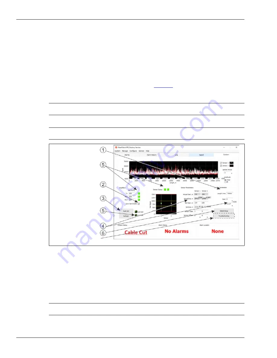
illustrates the System window for
the FP1150 Series sensor. The numbered points in the illustration correspond to the configuration
procedure that follows.
1.
Specify the Length Units for this installation. Length Units are Meters or Feet.
2.
Ensure that the Auto Gain Enable box is checked (default is checked).
Once the Auto Gain and Auto Bias indicators change from light green to dark green, wait at
least 30 seconds to ensure the Auto Gain process is complete, before proceeding with step 3.
3.
Once the Net Signal has stabilized between the 2 yellow lines, select the Auto Set button.
The Auto Set process may take several minutes to complete. While the Auto Set process is
running the System Status will indicate Initializing. The Auto Set process will match the Set
Start and Set End with the Actual Start and Actual End for each sensor. The Scales and
Offsets will be set to default values. The System Status should now be Armed.
CAUTION
The FP1150 configuration settings should be adjusted only by a factory
trained technician.
Note
If you change the Length Units you must restart the software for the
change to take effect.
Figure 69 FiberPatrol System configuration (installer access level)
Note
Wait for the Auto Set (length calibration) process to complete before
proceeding with the system configuration.
specify the Length Units
sensor unit icon
0 m point
licensed length to end point
detected cable cut
(installed length of sensor cable)
Set Points and Channel
Status indicators light green
verify Auto Gain Enabled
is checked
select the Auto Set button
dark green Auto Gain
dark green Auto Bias
check the Actual Start
and Actual End of
Sensor 1 and Sensor 2
Troubleshooting button
Global Setup button


