


MS6-SV-...-D-10V24
Festo – MS6-SV-...-D-10V24 – 1702a English
19
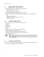
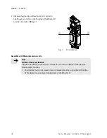
Proceed as follows when assembling with one or more service units from the same series (
è
Fig. 8):
1. Remove the MS6-END
1
cover cap, if present,
from the side to be assembled (slide upwards).
2. Insert a seal
2
between the individual units
(module connector MS6-MV or mounting
bracket MS6-WP/WPB included in the scope
of delivery).
3. Place the module connectors
3
in the slots of
the individual devices.
4. Fasten the module connectors with two
screws.
Fig. 8
Assembly
Max. 1.2 Nm
1
2
3


