


4.2.2
Position Transmitter Operating Mode (IO-Link)
In the position transmitter operating mode, programmed switching signals and
the continuous position values (digitally coded analogue values) are transferred.
–
Programming via IO-Link
–
Device description file IODD
è
–
Capacitive operating key is deactivated.
–
Proximity sensors or window comparators or hysteresis comparators can be
programmed individually on 4 switching channels.
–
The continuous position values are always transferred in parallel with and
independently of the position value output of the switching channels.
–
Each channel can be set to be normally closed (NC) or normally open (NO).
–
Data transfer is serially and digitally coded in the IO-Link protocol.
–
Process data: 12 bit for position data and 4 bit for switching channels
è
–
Unshielded standard cables of up to 20 m in length can be used.
–
Parameters and functions in accordance with Smart Sensor profile
–
Support for the optional functions “Block parameterisation” and “Data
storage”
–
The direction of increase of the process data values (PDV) can be inverted.
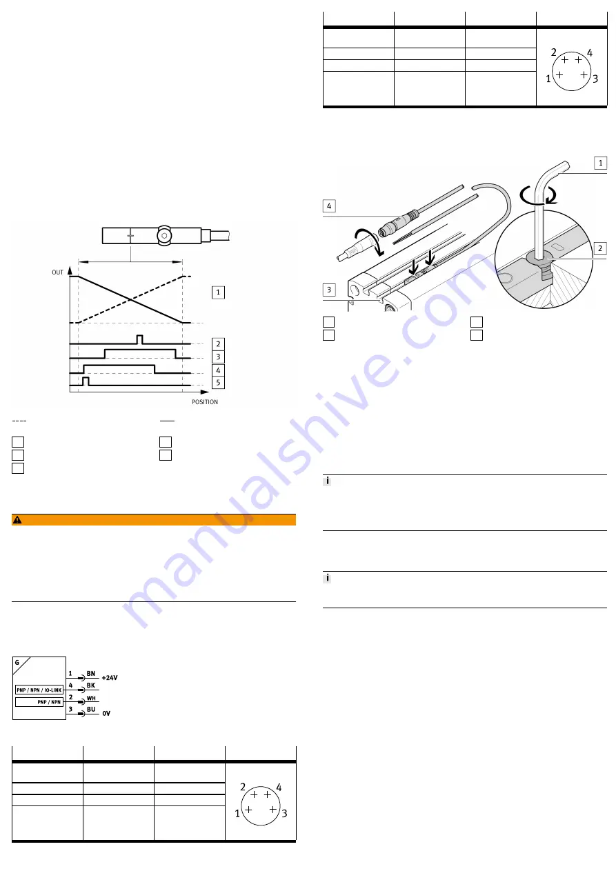
Delivery status: lowest PDV at cable end
Output signal (PDV): direction of
increase inverted
Output signal (PDV): direction of
increase as delivered
1 PDV (position data values)
2 SSC1 (switching signal channel)
3 SSC2
4 SSC3
5 SSC4
Fig. 3 Application example: Position transmitter operating mode
5
Electrical Installation
WARNING!
Risk of injury due to electric shock.
•
For the electrical power supply, use only PELV circuits in accordance with IEC
60204-1/EN 60204-1 (Protective Extra-Low Voltage, PELV).
•
Observe the general requirements of IEC 60204-1/EN60204-1 for PELV cir-
cuits.
•
Only use voltage sources that ensure a reliable electric separation from the
mains network in accordance with IEC 60204-1/EN 60204-1.
1. Switch off operating voltage.
2. Connect the M8 plug to the connecting cable of the higher-order controller
è
–
Tightening torque for the union nut of the plug: max. 0.3 Nm
Fig. 4 Circuit diagram
Pin
Wire colour
Allocation
Plug
1
Brown (BN)
Operating voltage
+24 V DC
2
White (WH)
Switching output 2
3
Blue (BU)
0 V
4
Black (BK)
Switching output 1
M8x1, 4-pin
Tab. 2 Pin Allocation of Plug Connection for Proximity Sensor Operating Mode
Pin
Wire colour
Allocation
Plug
1
Brown (BN)
Operating voltage
+24 V DC
2
White (WH)
Not used
3
Blue (BU)
0 V
4
Black (BK)
IO-Link
M8x1, 4-pin
Tab. 3 Pin Allocation of Plug Connection for Position Transmitter Operating Mode
6
Mechanical installation
1 Hexagon socket spanner
2 Retaining screw
3 T-slot (profile slot 8)
4 M8 plug
Fig. 5 Mechanical installation
1. Insert the position transmitter into the T-slot of the drive.
2. Move the piston into an end position of the application.
3. Push the position transmitter in the direction of the piston until the red LED
goes out.
4. Tighten the hexagon socket-head bolts (spanner size: 1.5 mm).
–
Tightening torque: max. 0.5 Nm
7
Commissioning
•
Switch on the operating voltage.
Ä
The position transmitter is ready for operation.
7.1
Proximity Sensor Operating Mode
The position transmitter is parameterised once it is installed.
•
Be mindful of the surface temperature of the capacitive operating key and of
the drive.
•
Avoid contamination and moisture on the position transmitter.
7.1.1
Activating set-up mode
•
Press the capacitive operating key 3 times within 3 s.
Ä
Set-up mode active: yellow and red LEDs flash alternately.
If programming is not completed within 60 s of starting set-up mode, the SDAS-
MHS automatically switches into the operating mode.


