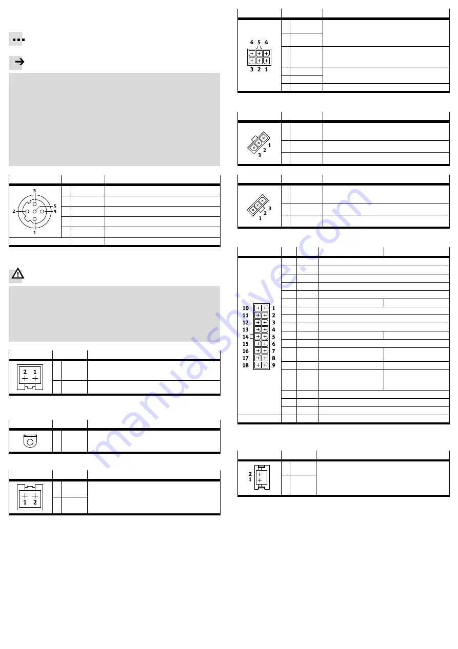
5.2 Parameterisation interface (Ethernet) [X1] – socket M12, 5-pin, D-coded
Connect the EMCA to your network or directly to the PC via a hub/switch. Observe
line specification (
è
Device and functional description, GDCE-EMCA-EC-DIO-...).
Recommendation: Use the connecting cable NEBC-D12G4-... from Festo.
Note
Unauthorised access to the device can cause damage or malfunctions.
When connecting the device to a network:
Protect the network against unauthorised access.
Measures to protect the network include:
– firewall
– intrusion prevention system (IPS)
– network segmentation
– virtual LAN (VLAN)
– virtual private network (VPN)
– security at physical access level (port security)
Additional information
è
Guidelines and standards for security in information
technology, e.g. IEC 62443, ISO/IEC 27001.
[X1]
Pin
Description
1
TD+
Transmitted data +
2
RD+
Received data -
3
TD-
Transmitted data –
4
RD-
Received data –
5
–
Not connected
Housing
Shield/F E
Shield/functional earth
5.3 Power supply [X4]
Warning
Danger of electric shock from voltage sources without safeguarding.
For the electrical power supply, use only PELV circuits (protective extra-low
voltage, PELV) in accordance with EN 60204-1.
Also observe the general requirements for PELV circuits in accordance with
EN 60204-1.
Use only voltage sources which guarantee reliable electrical isolation of
the operating and load voltage in accordance with EN 60204-1.
[X4]
Pin
Description
1
+24 V DC
Power supply (logic and load voltage)
+19.2 V DC … +28.8 V DC
2
0 V
GND, reference potential
If a screened supply cable is used, the cable screening can be connected to
the functional earth connection (flat plug).
Flat plug
Pin
Description
-
FE
Optional connection for the cable screening
counterplug: flat connector sleeve (6.3 x 0.8 mm²)
5.4 Braking resistor
[X5]
Pin
Description
1
ZK+
Connection for the external braking resistor R
BR
6
Ω
.
The braking resistor CACR-LE2-6-W60 from Festo is suitable.
2
BR-CH
5.5 STO interface [X6]
The STO safety function (safe torque off ) is described in detail in the document
GDCE-EMCA-EC-S1-.... The STO function should only be used in the manner
described in this document.
Recommendation for initial motor start-up without safety equipment:
– The setup must at least include an emergency stop switching device
– 2-channel switch-off via the control ports STO1 [X6.4] andSTO2 [X6.5]
[X6]
Pin
Description
1
NC1
Acknowledgment contact:
– Potential-free
– Low impedance if the STO function has been reques
ted and activated via 2 channels
2
NC2
3
+24 V DC
LOGIC OUT
Logic voltage output (from [X4.1]), pin [X6.6] or [X4.2] is
the reference potential (0 V) (internally bridged)
Not overload-proof! Max. 100 mA permissible.
4
STO 1
Control ports for STO function
5
STO 2
6
GND
Reference potential 0 V
5.6 End/reference switch [X7], [X8]
[X7]
Pin
Description
1
+24 V DC
Voltage output 24 V to power the reference or limit
switch 1 (configurable with FCT, not short-circuit safe).
2
Switch 1
Signal input for reference switch or limit switch 1
3
GND
Reference potential 0 V
[X8]
Pin
Description
1
+24 V DC
Voltage output 24 V to power the reference or limit
switch 2 (configurable with FCT, not short-circuit safe).
2
Switch 2
Signal input for reference switch or limit switch 2
3
GND
Reference potential 0 V
5.7 I/O interface [X9]
[X9]
Pin
Type
Mode 0
Mode 1
1
DIN
Record selection 1
2
DIN
Record selection 2
3
DIN
Record selection 4
4
DIN
Record selection 8
5
DIN
Record selection 16
6
DIN
Record selection 32
Jog+
7
DOUT
Ready
8
DOUT
configurable
9
–
Output 24 V DC, looped through from [X4.1]
10
DOUT
Acknowledge
Setpoint Acknowledge
11
DOUT
Motion Complete
12
DIN
Control mode 0/1
Low level = mode 0
Control mode 0/1
High level = mode 1
13
DIN
Start
Teach
14
DIN
Brake control/Delete
remaining path
Jog–
15
DIN
Stop
16
DIN
Control enable/Acknowledge error
17
–
Do not connect
18
–
GND (reference potential)
1)
DIN = digital input; DOUT = digital output
5.8 External battery [X10] – only EMCA-EC-...-1TM
[X10]
Pin
Description
1
B
Connection for external battery (Position changes are
recorded for up to 7 days without supply voltage and
without battery (after charging for approx. 24 hours)). With
the EADA-A-9 battery from Festo, the duration is extended
up to 6 months.
2
Battery –
(GND)
5.9 Ensuring the IP degree of protection
Comply with requirements for securing the IP degree of protection
(
è
Device and functional description, GDCE-EMCA-EC-DIO-...).
6
Commissioning
Communication of the product with a connected PC takes place via the TCP/IPv4
protocol.
Create network connection – example “point-to-point connection”
Requirement:
– The PC is configured as a DHCP client (usually the default setting for PCs).
– The EMCA is configured as a DHCP server (factory setting).
At initial commissioning, connect the EMCA directly to the PC.
Factory setting
DHCP server: active
IP address: http://192.168.178.1
Subnet mask: 255.255.255.0
Gateway: - (A gateway is not assigned.)


