


Connecting sealing air
The use of sealing air at approx. ± 0.02 MPa (± 0.2 bar, ± 2.9 psi) reduces or
prevents subsequent contamination:
–
The application of negative pressure minimises the release of abraded particles
into the environment.
–
The application of overpressure reduces the penetration of dirt into the
drivetrain.
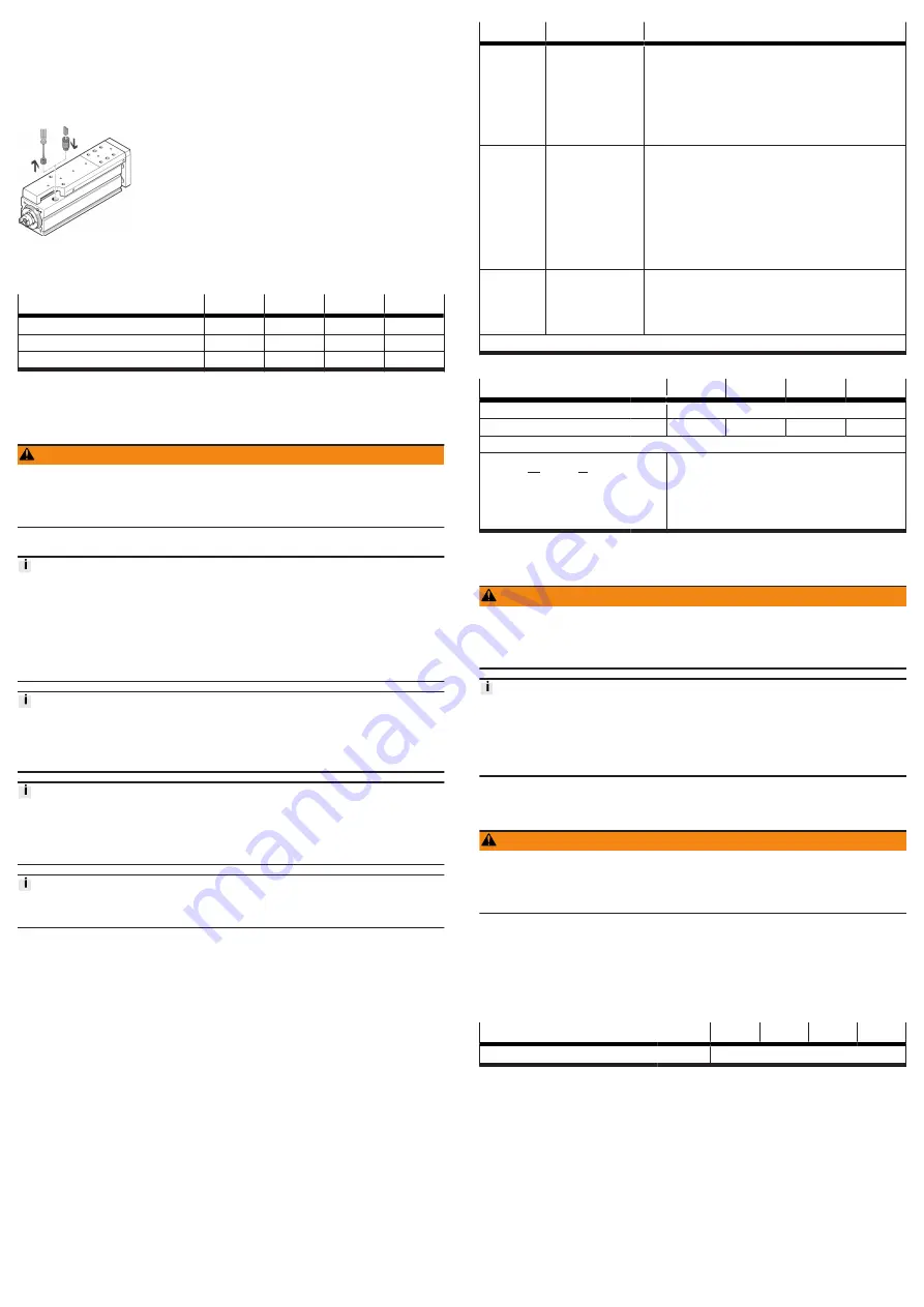
Fig. 3: Mounting fitting
1. Remove the filter element from the threaded hole.
2. Mount the screw fitting and connect the hose.
Size
25
32
45
60
Thread
M5
M5
G 1/8
G 1/4
Max. screw-in depth
[mm]
4
5
7
7
Max. tightening torque
[Nm]
1.4
1.4
5
8
Tab. 8: Information on sealing air connection
7
Commissioning
7.1
Safety
WARNING
Risk of injury due to unexpected movement of components.
• Protect the positioning range from unwanted intervention.
• Keep foreign objects out of the positioning range.
• Perform commissioning with low dynamic response.
7.2
Performing commissioning
Block-shaped acceleration profiles without jerk limitation can have the following
effects:
• High mechanical loads on the lead screw due to high force peaks.
• Overshooting effects during positioning.
• Rise of the entire system.
Recommendation: reduce high force peaks in the acceleration and deceleration
phases by using the jerk limitation.
When the motor is removed, the motor encoder loses its absolute reference to the
reference mark, e.g. by turning the motor drive shaft.
• Carry out a homing run every time the motor is mounted in order to establish
the absolute reference between the motor encoder and the reference mark.
Running noises during operation
Identically constructed sliding drives can generate different running noises
depending on the parameterisation, mode of operation, type of mounting, instal-
lation environment and components.
For use with reduced particle emission
Clean product
Requirement
–
Mounting of the drive system s checked.
–
Installation and wiring of the motor is checked.
–
No foreign objects in the movement space of the drive system.
–
Maximum permissible feed force and drive torque not exceeded as a function
of acceleration, deceleration (e.g. stop function, quick stop), velocity, moving
mass and mounting position.
–
Mini slide not mechanically overloaded and dynamic setpoint deviation not
exceeded due to force and torque peaks or overshoot effects, e.g. overrunning
the end position.
Limit overloads and overruns by jerk limitation, reduced acceleration and decel-
eration setpoints or optimised controller settings.
–
Control run and reference run with reduced speed setpoints, acceleration set-
points and deceleration setpoints.
–
No test run to mechanical end stops.
–
Software end positions ≥ 0.25 mm away from the mechanical stops.
Steps
Purpose
Note
1. Check
travel
Determining the
direction of travel of
the slide
–
Direction of movement of the slide, clockwise spindle:
–
Retracting: rotate drive shaft clockwise.
–
Advancing: rotate drive shaft anti-clockwise.
–
The direction of movement of the slide for positve and
negative position values depends on the mounting posi-
tion of the motor on the slide, e.g. parallel kit or axial kit.
–
Set a required reversal of direction of rotation via param-
eters in the servo drive or controller.
2. Homing
Determination of
the reference point
and adjustment of
the dimensional ref-
erence system
–
during the initial
start-up proce-
dure
–
after replacement
of the motor
Permissible reference points:
–
towards reference switch:
Travel at reduced velocity
–
towards end position:
do not exceed maximum values
Additional information
è
Instruction manual of the drive
system
3. Test run
Checking the oper-
ating conditions
Check application requirements:
–
Slide travels through the complete travel cycle in the
specified time.
–
The slide stops travel when a limit switch or software end
position is reached.
After a successful test run, the drive system is ready for operation.
Tab. 9: Commissioning steps
Size
25
32
45
60
Max. stop velocity
[m/s]
0.01
Max. stop energy
[mJ]
0.005
0.009
0.014
0.044
Calculation of the maximum stop energy
•
!"
=
$
%
2 &m +
'
(
'
)
*
–
v = max. stop velocity
–
m = mass of all linear moving components
–
J
R
= mass moment of inertia of all rotating compo-
nents
–
J
L
= mass moment of inertia per kg payload
Tab. 10: Speed and energy at the end positions
8
Operation
WARNING
Risk of injury due to unexpected movement of components.
• Protect the positioning range from unwanted intervention.
• Keep foreign objects out of the positioning range.
• Perform commissioning with low dynamic response.
Lubrication run during operation
Observe the following lubrication travel intervals.
• With working stroke less than 2 x spindle pitch... P:
• Perform a lubrication run within 10 travel cycles with a minimum stroke of
≥ 2 x spindle pitch.
9
Maintenance
9.1
Safety
WARNING
Unexpected movement of components.
Injury due to impacts or crushing.
• Before working on the product, switch off the control and secure it to prevent it
from being switched back on accidentally.
9.2
Checking slide elements
Checking reversing backlash
•
Check the reversing backlash (reversal error) of the slide at every mainte-
nance interval, e.g. lubrication interval.
If the maximum permissible reversing backlash is exceeded, the slide should
be replaced.
Size
25
32
45
60
Max. permissible reversing backlash
[mm]
£
0.15
Tab. 11: Maximum permissible reversing backlash
9.3
Cleaning
–
If the piston rod is dirty, clean it with a clean, soft and lint-free cloth without
cleaning agents and then apply the lubricant thinly to the piston rod.
–
Clean the other product components with a clean, soft cloth and non-abrasive
cleaning agents.
For use with reduced particle emission:
–
Remove abrasion and contamination from the product on the following
schedule:
–
Prior to initial commissioning.
–
Regularly during operation.


