DHPC
Parallel gripper
Festo SE & Co. KG
Ruiter Straße 82
73734 Esslingen
Deutschland
+49 711 347-0
www.festo.com
Operating instructions
8150807
2021-05a
[8150809]
Translation of the original instructions
© 2021 all rights reserved to Festo SE & Co. KG
1
Applicable Documents
All available documents for the product
2
Safety
2.1
Safety Instructions
–
Take into consideration the ambient conditions at the location of use.
–
Only use the product in original status without unauthorised modifications.
–
Observe labelling on the product.
–
Store the product in a cool, dry, UV-protected and corrosion-protected environ-
ment. Ensure that storage times are kept to a minimum.
–
Prior to mounting, installation and maintenance work: Switch off compressed
air supply and secure it from being switched back on.
–
Observe tightening torques. Unless otherwise specified, the tolerance is
± 20 %.
2.2
Intended use
The intended use of the product is to grip and hold payloads (workpieces) using
custom-designed gripper fingers attached by the customer.
2.3
Training of qualified personnel
Installation, commissioning, maintenance and disassembly should only be con-
ducted by qualified personnel.
The specialized personnel must be familiar with the installation and operation of
electrical and pneumatic control systems.
3
Additional information
–
Contact the regional Festo contact if you have technical problems
–
Accessories and spare parts
4
Product overview
4.1
Function
–
Alternating pressurisation of the supply ports causes a piston in the gripper to
move (double-acting).
–
A gripper with integrated spring return is used to exert the gripper force. When
exhausting the single-acting gripper: the spring return moves the gripper jaws
to the initial position.
–
N/O contact: NO (normally open)
–
N/C contact: NC (normally closed)
–
The piston movement is transmitted mechanically to the gripper jaws. Gripper
fingers are fastened to the gripper jaws. Closing or opening the gripper fingers
clamps the payload to the outer contour (external gripping) or the inner contour
(internal gripping).
–
The gripping force is adjusted by external regulation of the operating pressure.
–
The gripper has integrated fixed flow restrictors. If the max. gripper finger
weights and the max. gripper finger lengths are in compliance, an external flow
control is not required.
4.2
Structure
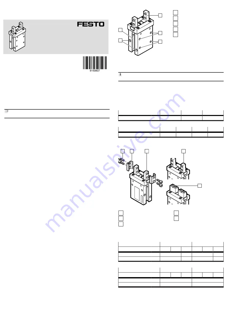
1
2
3
4
5
Fig. 1: Structure
1
Gripper jaw
2
Threaded hole for mounting
3
Locating hole
4
Supply port
5
Slot for proximity switch
5
Assembly
5.1
Preparing the gripper fingers
The gripper fingers are not included in the delivery.
Requirements for the gripper fingers
–
Observe the max. permissible forces and max. permissible torques at the
gripper jaw.
–
Observe the max. length and max. weight.
–
Use gripper fingers that are as short and light as possible.
–
Manufacture gripper fingers that are suitable for the payload and type of grip-
ping action.
Size
6
10
16
Width at gripper jaws
[mm]
4.3
–0.05
5.4
–0.05
7
–0.05
Tab. 1: Width of gripper jaws
Size
20
25
32
40
Width at gripper jaws
[mm]
8.3
–0.05
12
–0.05
15.2
–0.05
18
–0.05
Tab. 2: Width of gripper jaws
5.2
Mounting the gripper fingers
1
2
3
4
5
Fig. 2: Mounting the gripper fingers
1
Screw
2
Gripper finger
3
Gripper jaw A
4
Gripper jaw A-...-1
5
Gripper jaw A-...-2
•
Position the prepared gripper fingers [2] on the gripper jaws [3], [4], [5] and
fasten each one with two screws [1]. Fix the gripper jaws in place during
mounting and use the specified tightening torque.
DHPC
-6-...
-10-...
A
A-...-1 A-...-2 A
A-...-1 A-...-2
Screw
M3
M2
M3
M2.5
Tightening torque
[Nm]
0.59
0.15
0.59
0.31
Tab. 3: Dimensions and tightening torque
DHPC
-16-...
-20-...
A
A-...-1 A-...-2 A
A-...-1 A-...-2
Screw
M3
M4
Tightening torque
[Nm]
0.59
1.4
Tab. 4: Dimensions and tightening torque


