Disassembly
Switch off the energy supplies in the following sequence to allow the integrated
valve block to safely vent the drive:
1. First switch off the operating voltage supply.
2. Only after that switch off the compressed air supply.
Only when the drive is vented can the piston rod be shifted manually, for example
to push the piston rod in for safe transport.
Repair
Repairs to the product are only permissible by Festo's repair service.
10
Fault clearance
Malfunction
Possible cause
Remedy
The DFPI closes the
process valve, even
though a different
setpoint is specified.
Operating voltage supply or the analogue
setpoint is outside of the permitted range
(e.g. in the event of a wire break); the DFPI
moves to the safety position
Check operating
voltage supply and
analogue setpoint
Even though the energy
supply is switched off, the
piston rod cannot be
shifted manually.
The drive has not been vented because
the compressed air supply was switched
off first, and then the operating voltage
supply.
First switch off the op
erating voltage supply,
and then the com
pressed air supply.
Current at the analogue
output
3.5 mA
Device errors
Check operating
voltage supply,
operating pressure
and analogue setpoint
Current at the analogue
output = 21.0 mA
The device must be taught
Initialise device
Current at the analogue
output = 21.5 mA
Device is in teach-in status
–
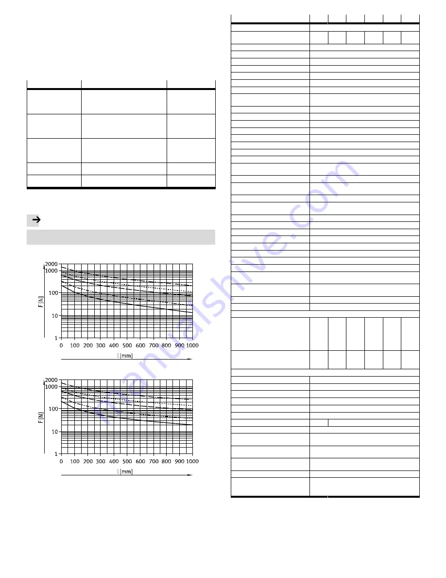
Fig. 10
Max. permissible lateral force for static application
Note
In controlled operation, adjustment of the max. lateral force to the type of con
trol may be required.
Horizontal mounting
Vertical mounting
Fig. 11
11
Technical data
DFPI-…-C1V-NB3P-A
-100
-125
-160
-200
-250
-320
Type of mounting
Mounting interface in accordance with ISO 15552
Width across flats, spanner flat on the
piston rod
22
27
36
36
46
55
Stroke
[mm]
40…990
Min./max. stroke allowance
[mm]
0…4
Design
Piston rod, cylinder barrel
Cushioning
No cushioning
Assembly position
any
Mode of operation
Double-acting
Position sensing
With integrated displacement encoder
Measuring principle of displacement
encoder
Potentiometer
Electrical connection
5-pin; straight plug; screw terminal
Operating voltage range
[V DC]
24 ± 10 %
Nominal operating voltage
[V DC]
24
Max. current consumption
[mA]
220 (at 24 V DC)
Idle current
[mA]
40 (at 24 V DC)
Analogue input
[mA]
4…20
Max. load of the analogue input
[Ω]
Max. 500
Analogue output
[mA]
4…20
Max. load of the analogue
output
[Ω]
Max. 600
Accuracy of analogue output
[% FS]
±1
Analogue output response
time
[ms]
< 100
Initialisation input
[V DC]
22.8…26.4; I = 11 mA at 24 V DC
Protection against polarity reversal
Operating voltage, setpoint value, initialisation connec
tion
Max. cable length
[m]
15
Positioning accuracy
[% FS]
1.0
Repetition accuracy
[% FS]
±1.0
Hysteresis
[% FS]
±1.0
Size of the dead zone
[% FS]
1.0
Operating pressure
[bar]
3…8
Nominal operating pressure
[bar]
6
Operating medium
Compressed air to ISO 8573-1:2010 [7:4:4]
Note on the operating medium
Operation with lubricated medium possible (in which
case lubricated operation will always be required)
Degree of protection - in mounted
status
IP65, IP67, IP69K, NEMA 4
Ambient temperature
[°C]
–5…+50
Relative air humidity
[%]
5…100, condensing
Product weight
Basic weight with 0 mm stroke
– DFPI
-…-
ND2P-C1V-P
[g]
5 280
7 950
14 330
20 410
35 370
57 550
– Additional weight per
10 mm stroke (not moving
mass)
[g]
90
134
200
238
358
582
Moving mass with 0 mm stroke
[g]
1060
1900
3700
4800
9300
16500
– Additional weight of moving
mass per 10 mm stroke
[g]
28
53
89
89
134
227
Note on materials
– Cylinder barrel
Anodised wrought aluminium alloy
– Cap (end cap)
Coated wrought aluminium alloy
– Bottom cap (bearing cap)
Coated die-cast aluminium
– Tie rods
High-alloy stainless steel
– Piston rod
High-alloy stainless steel
– Flange screws/nuts
Coated steel
– Piston rod seals
PUR
NBR
– Static seal
NBR
Note on materials
RoHS-compliant, contains paint-wetting impairment
substances
Vibration resistance in accordance with
DIN/IEC 68, Part 2-6
0.35 mm travel at 10...60 Hz;
5 g acceleration at 60 ... 150 Hz
Continuous shock resistance
in accordance with DIN/IEC 68 Part 2-82
± 15 g at 6 ms duration,
1000 shocks per direction
Certification certificate
RCM
CE certification (see declaration of con
formity
è
www.festo.com)
in accordance with EU EMC Directive
1)
in accordance with EU Explosion Protection Directive
(ATEX)
2)
1)
The device is intended for use in an industrial environment. Outside of industrial environments, e.g. in
commercial and mixed-residential areas, actions to suppress interference may have to be taken.
2)
Certification-specific special documentation must be considered (
è
www.festo.com/sp).
Fig. 12


