5.2
Function
In the DAPS, the movement of the piston is transformed using a Scotch yoke sys-
tem into a swivel motion of the transmission shaft. This kinematic system is only
effective within an angle of approx. 90°.
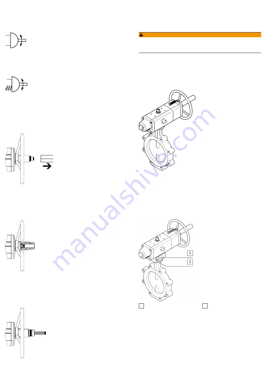
Double-acting semi-rotary drives
Fig. 2 Symbol – double-acting semi-rotary drive
Pressurising and exhausting the cylinder chambers causes the shaft to move back
and forth. The linear motion of the shaft is transformed into a swivel motion.
Single-acting semi-rotary drives
Fig. 3 Symbol – single-acting semi-rotary drive
Return is through spring force.
5.2.1
Manual override
The handwheel can be used to change the position of the drive with the supply
pressure switched off (manual override). The indicator for the position can be
seen by removing the conduit.
Neutral position
Fig. 4 Neutral position
–
Indicator is visible and end face lines up with the end of the pipe (mid-posi-
tion).
–
Piston can move freely.
–
Drive can be driven pneumatically.
Indicator inward
Fig. 5 Indicator inward
–
Double-acting drive: turning the handwheel anti-clockwise moves the indicat-
or inward. The valve opens.
–
Single-acting drive: turning the handwheel clockwise moves the indicator
inward. The valve closes.
Indicator outward
Fig. 6 Indicator outward
–
Double-acting drive: turning the handwheel clockwise moves the indicator
outward. The valve closes.
–
Single-acting drive: turning the handwheel anti-clockwise moves the indicator
outward. The valve opens.
6
Transport and storage
WARNING!
Danger of crushing. Danger of shearing.
Body parts can be crushed or severed if the product falls.
•
Use appropriate load handling equipment.
•
When dispatching used products: Comply with all legal requirements for the
handling of hazardous substances and the transport of dangerous goods. For
return to Festo
è
•
Remove all attachments.
7
Assembly
7.1
Assembly without adapter plate
Fig. 7 Assembly without adapter bridge
1. Place the semi-rotary drive on the control shaft of the process valve. The
square of the process valve must sit in the coupling of the semi-rotary drive
(
è
aB
) without tilting.
2. Mount the semi-rotary drive on the connecting flange of the process valve
using 4 corrosion-resistant screws and retaining rings (material: CI).
3. Tighten the screws crosswise.
–
Tightening torque
è
7.2
Assembly with adapter bridge
1 Shaft extension
2 Adapter bridge
Fig. 8 Assembly with adapter bridge
1. Have adapter bridge and shaft extension ready.
2. Mount the adapter bridge (
è
) on the semi-rotary drive.
–
Align studs of the adapter bridge lengthwise to the drive.
–
Insert screws, but do not yet fully tighten.
3. Insert shaft extension (
è
). The square of the shaft extension must
sit in the coupling of the semi-rotary drive (
è
aB
) without tilting.
4. Place the semi-rotary drive with adapter bridge and shaft extension on the
control shaft of the process valve. The square of the process valve must sit in
the coupling of the shaft extension without tilting.
5. Mount the adapter bridge on the connecting flange of the process valve using
4 corrosion-resistant screws and retaining rings (material: CI).


