

5.4
Setting up control system, creating automation
project
è
Documentation of the control system
Example of Siemens SIMATIC S7-1200, TIA portal:
1. Open device and network view:
View
è
Double click “Devices & networks”.
2. Open “Network view”.
3. Open hardware catalog (“Catalog”).
4.Open “System control” (“PLC”) directory.
5. Drag system control (PCL/“CPU”) into the network view.
5.5
Insert PROFINET station (“Station”)
è
Documentation of the control system
Example of Siemens SIMATIC S7-1200, TIA portal:
1. Open “Devices & networks” view
è
Section 5.4).
2. Open “Network view”.
3. Open hardware catalog (“Catalog”).
4.Open “Other field devices” directory:
è
“PROFINET IO”
è
“Valves”
è
“Festo AG & Co. KG”
è
“Festo CTEU-PN”.
5. Select the symbol for the PROFINET station, i.e. of bus
node CTEU-PN and drag it into the network view.
6. Open “Connections” view.
7. Connect bus node CTEU-PN to the control system:
Click bus node symbol, press and hold down button and
drag mouse pointer to system control symbol.
8. Select connection: “Connections”
è
“PROFINET IO
system”.
5.6
Assigning a “Device Name”
è
Documentation of the control system
With the device name, you can address the bus node and
the connected product (“I-port device”) directly, e.g. in
your automation program.
5.7
Assigning or changing IP address
è
Documentation of the control system
In most cases, the control system handles the assignment
of an IP address.
Note
. . . . . . . . . . . . . . . . . . . . . . . . . . . . . . . . . . .
Observe the basic addressing rules for the allocation
of the IP address, e.g. with respect to the use of
private or public address ranges.
Check that the IP address can be used in the automa
tion network.
Ensure that there is no duplication of IP addresses in
use.
5.8
Configuring field devices (“I-port devices;)
è
Documentation of the control system
Example of Siemens SIMATIC S7-1200, TIA portal:
1. Open “Devices & networks” view
è
Section 5.4).
2. Open “Device view”.
3. Open hardware catalog (“Catalog”).
4.Open “Other field devices” directory.
5. Configure field devices:
Drag the symbols for the connected products (“I-port
devices”) into the “Device overview”.
5.9
Changing start addresses of inputs/outputs
è
Documentation of the control system
In most cases, the control system handles the assignment
of the input/output addresses and the diagnosis ad
dresses.
5.10
Setting up PROFINET “Fast Start-up” function
è
Documentation of the control system
Note
. . . . . . . . . . . . . . . . . . . . . . . . . . . . . . . . . . .
When using the PROFINET “Fast Start-up” function
(FSU), “Crossover Detection”, “Auto-MDI” and
“Autocrossover/Autonegotiation” are
not
available.
Crossover detection -
disable
:
– in the hardware configuration of
all
network
participants
– in the hardware configuration of the network
neighbor (“Partner Port”).
Deactivation of the crossover detection changes
changes the pin allocation of the next network port TP2
to “crossover”.
Select interconnecting cable dependent on pin
assignment of network connection of product
connected to TP2:
– Crossover cables with
identical
assignment of
ports
– Patch cables with
different
assignment of ports.
Example of Siemens SIMATIC S7-1200, TIA portal:
1. Call up “Device overview” :
Open “Project navigation” window
è
Devices
è
Device view
è
Device overview
è
Module
è
CTEU-PN.
2. Click “PN-IO Interface” module.
3. Call up interface options:
Window for “PN-IO Interface [Module]”
è
Properties
è
General
è
Advanced options
è
Interface options.
4.Enable interface option “Prioritized start-up (tick
boxes).
5. Call up port options:
Window “PN-IO Interface [Module]”
è
Properties
è
General
è
Advanced options
è
“Port 1 [X1 P1 R]”
and/or “Port 2 [X1 P2 R]”
è
Port options.
6. Under “Connection”,
disable
crossover detection
(“Autonegotiation”) on network ports TP1
and
TP2.
5.11
Set parameterisation
è
Documentation of the control system
You can set the characteristics of connected products
individually using parameterisation (“Module paramet
erisation”), e.g. input debounce time, signal extension
time, product monitoring, (forwarding of diagnostic mes
sages), settings for error situations (“Fail-state” mode).
Parameterisation for “I-port device” 1 (X1) and “I-port
device” 2 (X2) can be set separately.
Parameter
1)
Function
Port settings
2)
Example “Universal device 256DIO”
Tool Change Mode
Tool change mode:
– “Tool Change Mode” enabled:
The process data image rigidly assigns
address spaces for input and output
data (addressed) – regardless of which
product is connected (“I-port device”),
meaning that the connected products
(e.g. tools) can be interchanged without
the need for any configuration changes.
– “Tool Change Mode” disabled:
The “I-port device” detected at start-up
is adopted by the PROFINET configura
tion. The assignment (addressing) of in
put and output data in the process data
image depends on the connected
product.
Suppress all dia
gnostic messages
No forwarding of diagnostic messages via
the network
Suppress
diagnostic message
“No load voltage”
No forwarding of diagnostic message
“No load voltage”
3)
via the network
4)
(“Suppress missing load voltage diagnostic
messages”)
Fail-state
The “Fail-state” mode governs the charac
teristics of the bus node and the connected
products in the event of any communica
tion errors arising:
– Reset outputs (“Outputs reset”): The
outputs are reset.
– Outputs “Hold last state” (“Outputs
Hold last state”): The outputs hold their
last state.
The selected setting applies to all outputs.
The “Fail-state” setting also applies to the
“Idle state” operating state:
– The “Idle state” is adopted by the con
trol system on request. At this point, the
control system is in “Stop mode”.
– Input data continue to be transmitted
while the system is in “Idle state”.
I-port device parameter
2)
Example “Universal device 256DIO”
Byte 0 ... Byte 7
Tunneling of product-specific parameters
è
Documentation about the connected
product
1) Siemens SIMATIC S7-1200, TIA portal: Module parameter(s)
2) The available parameters depend on the connected product.
3) Monitoring for undervoltage of load voltage power supply to
outputs/valves U
OUT/VAL
(“Undervoltage U
OUT/VAL
”)
4) Diagnostic messages “No load voltage” are only generated once,
whenever the connected product is monitoring load voltage and
repor ts this status to the bus node.
Note
. . . . . . . . . . . . . . . . . . . . . . . . . . . . . . . . . . .
Functional test
– The LED
NF
is OFF (subject to fault-free communica
tion between control system and bus node).
– The LED
TP1
or
TP2
lights up green (
è
Section 7).
– Siemens SIMATIC S7-1200, TIA portal: In the
columns for “I address” and “O address”
respectively, the address entries are located (start
addresses for the inputs/outputs).
– Check availability of the network participants:
Menu “online”
è
“Accessible devices”
è
Check list
ing of available network participants for complete
ness (“Accessible devices in target subnet”).
6 “Identification and Maintenance”
è
Documentation of the control system
The “Identification and Maintenance” (I&M) function of
fers uniform, manufacturer-independent access to
product-specific information.
Note
. . . . . . . . . . . . . . . . . . . . . . . . . . . . . . . . . . .
Manually updated I&M details, e.g. about the firmware
and software state of the bus node can differ from the
details on the product nomenclature.
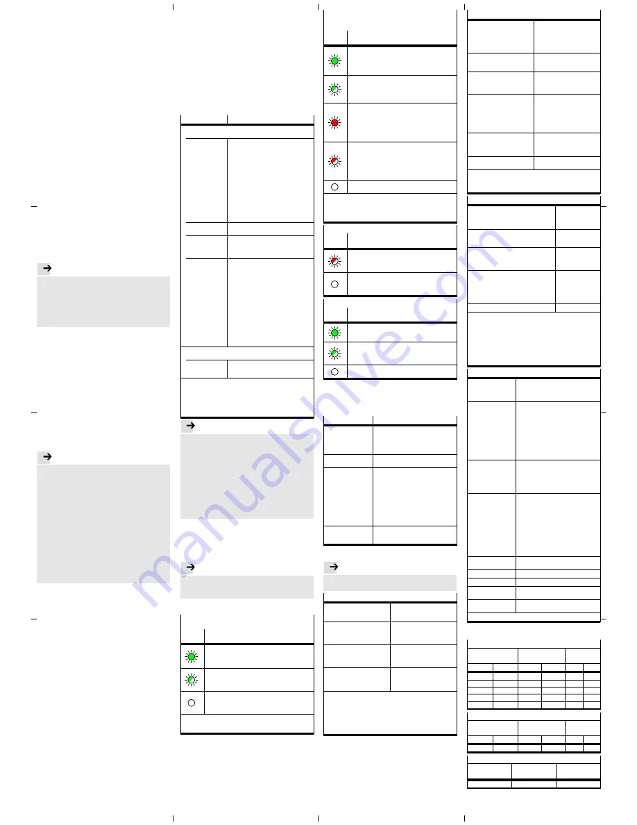
7 Diagnostics
PS – Status of the operating voltage supply
(power system)
LED
display
Status and significance
LED illuminated green:
– normal operating status
– Operating voltage is ON (within permitted range)
– Load voltage is ON (within permitted range)
1)
LED flashes green (flashing frequency: 1 Hz)
– Operating voltage is below the required voltage
– Load voltage is below the required level
1)
– Short circuit at the I-port
1)
LED is off:
– Operating voltage not present
– Operating voltage is below the voltage required for
diagnostic functions
1) This display only relates to the status of the load voltage if the
the connected product is monitoring the load voltage and
repor ts its status to the bus node.
X1 and X2 – Status of internal communication between
the bus node and the connected product
(“I-port device” 1 or “I-port device” 2)
1)
LED
display
Status and significance
LED illuminated green:
– normal operating status
– “I-port device” 1 or 2 is connected up correctly
– Operating and load voltage are connected (within
permitted range)
2)
LED flashing green:
– Status of diagnostics
– Undervoltage at system or additional power supply
– Connection between the bus node and the “I-port
device” is OK
LED illuminated red:
– “I-port device” is connected up correctly, but the
internal communication is in a fault state
– After start-up, wrong “I-port device” is connected up
(not the “I-port device” specified in the control
system hardware configuration, or a product not
compatible with I-port)
LED flashing red:
– During commissioning, incorrect I-port device
connected (non-I-port-compatible device)
– If only LED X1 flashes red: error in the bus node
– If X1 and X2 flash red simultaneously: no product
connected to the bus node (at least one I-port device
is required)
LED is off:
– No product connected to the bus node
1) Accessory with two I-port interfaces required to connect up two
products
2) This display only relates to the status of the load voltage if the
the connected product is monitoring the load voltage and
repor ts its status to the bus node.
NF – Network status/network failure
LED
display
Status and significance
LED flashing red:
– Communication error
– Communication between control system and bus
node is malfunctioning or interrupted.
LED is off:
– normal operating status
– Communication between control system and bus
node is OK
TP1/TP2 – Connection status (“Link” 1 or “Link” 2)
LED
display
Status and significance
LED illuminated green:
– normal operating status
– Network connection is OK
Both LEDs, TP1 and TP2 flash green:
– To locate the connected product (“module location”),
e.g. during hardware configuration of control system
or for troubleshooting
LED is off:
– No network connected
8 Maintenance
No specific measures
9 Glossary
Term/abbreviation Function
FSU
PROFINET function “Fast Start-up” also
known as “Prioritized Start-up” or “Fast
reboot”; operating mode of bus node,
assures fast rebooting of network
participants (“IO devices”)
PROFIenergy
PROFIenergy facilitates energy
management settings
PROFINET
Network and field bus system based on
Industrial Ethernet for data interchange
between a primary control system
(industry PC, PCL or “IO controller”),
network participants (“IO devices”) and
field devices (“Field Devices”), e.g. valve
terminals or drives
è
www.profinet.com
è
www.profibus.com/download/
è
PROFINET System Description,
Technology and Application
PLC
Programmable logic controller, also
referred to as system controller or
controller for short (PLC)
10 Technical data
Note
. . . . . . . . . . . . . . . . . . . . . . . . . . . . . . . . . . .
Technical data for the connected products can be ob
tained from the product documentation.
Electrical properties
Protection class through housing
(in accordance with
IEC/EN 60529/EN 60529)
IP65/IP67
1)2)
Protection against electric shock
(protection against direct and
indirect contact to
IEC 60204-1/EN 60204-1)
through the use of PELV circuits
(Protected Extra-Low Voltage)
Separation
Network connections for
operating voltage power supply
U
EL/SEN
Galvanically separated through
transformer (up to 500 V)
Electromagnetic compatibility
(EMC)
3)
– Emitted interference
– Resistance to interference
See declaration of conformity
è
www.festo.com
1) Requirement: Bus node mounted completely, plug connector in
the plugged-in status or provided with cover cap.
2) Connected products may only satisfy a lower degree of
protection.
3) The product is intended for use in an industrial environment.
Outside of industrial environments, e.g. in commercial and
mixed-residential areas, actions to suppress interference may
have to be taken.
General mechanical attributes
Vibration and shock resistance
(in accordance with
IEC/EN 60068)
1)
– Vibration (part 2-6)
– Shock (part 2-27)
– Continuous shock (part 2-27)
Severity level (SL)
1)
for wall or
H-rail mounting
– Wall: SG2; H-rail: SG1
– Wall: SG2; H-rail: SG1
– Wall and H-rail: SG1
Temperature range
2)
– Storage/transpor t
– Operation
–20 … +70 °C
–5 … +50 °C
Corrosion protection
The product is intended for
indoor application in typical
industrial atmosphere: Avoid
condensation.
Materials
– housing
– fibre-optic cable
– Threaded sleeve M12
– Threaded bush M3
– Seals
– Screws
RoHS-compliant
Reinforced polyamide
Polycarbonate
Brass, galvanically nickel-plated
brass,
Nitrile rubber
Galvanised steel
Dimensions
– Width
– Length
– Height
40 mm
91 mm
50 mm
Weight (bus node without cables
and sub-assembly)
94 g
1) Explanation of the severity level
è
Table “Explanation on
vibration and shock – severity level”
2) Connected products may only satisfy a less extensive
temperature range.
Power supply
Operating voltage for bus node and
connected products
1)
– Nennwert
– tolerance range
24 V DC
18 … 30 V DC
2)
Load voltage for bus node and connected
products
1)
– Tolerance range
18 … 30 V DC
2)
Intrinsic current consumption at nominal
operating voltage 24 V DC
from operating voltage supply for
electronics/sensors (U
EL/SEN
)
Typically 80 mA
(internal electronics)
Power rating of operating and load voltage
power supplies
1)3)
– Bus node on the connected product
(e.g. valve terminal)
– Bus node on the decentralised electric
sub-base CAPC
max.
4 A
max.
2 A
per “I-port device”
4)
Power failure buffering
10 ms
1) Separate and external fuses are required for the operating and
load voltage power supplies (no bus node-internal overload and
polarity reversal protection for the connected products).
2) The tolerance range is dependent on the connected products.
3) Total power rating of operating and load voltage power supplies
PS and PL (residual current), maximum permitted current
consumption of bus node and connected products
4) Total power rating of operating and load voltage power supplies
PS and PL (residual current), maximum permitted current
consumption for each “I-port device”
Network-specific characteristics
Network protocol
PROFINET IO:
– based on Industrial Ethernet
– based on the standard Ethernet
protocol (IEEE 802.3)
Suppor ted protocol
characteristics and
protocol functions
(selection)
– Cyclical data exchange “in real time”,
without cycle synchronicity (Real-Time,
RT) or with cycle synchronicity
(Isochronous Real Time, IRT)
1)
– Link Layer Discovery Protocol (LLDP)
– Simple Network Management Protocol
(SNMP)
– Fast Start-up (FSU)
– PROFIenergy
– Shared device
– Media Redundancy Protocol (MRP)
System-specific
functions
– Diagnosis information (system
diagnosis, undervoltage,
communication errors)
– Web server (status of bus node and
connected products, serial number,
configuration)
Specification
Selection of directives and norms
regarding PROFINET:
– PROFINET installation guidelines
(“PROFINET Installation Guide”,
“Installation Guideline PROFINET
Part 2…”).
– IEC 61158
– IEC 61784
– IEC 61918
For additional information:
è
www.profinet.com
è
www.profibus.com/download/
Transmission
technology
Switched Fast EtherCat;
Version 100BaseTX acc. to IEEE 802.3
Transmission rate
100 Mbit/s
Network connections
2 x socket, M12, D-coded, 4-pin
Crossover detection,
auto-negotiation
Auto-M DI
Max. address volume
inputs/outputs
64 bytes E, 64 bytes A,
independent of operating mode
1) IRT is only available via LAN
Explanation on vibration and shock – severity level
Vibration load
Frequency range
[Hz]
Acceleration
[m/s
2
]
Displacement
[mm]
SL1
SL2
SL1
SL2
SL1
SL2
2 … 8
2 … 8
–
–
±3.5
±3.5
8 … 27
8 … 27
10
10
–
–
27 … 58
27 … 60
–
–
±0.15
±0.35
58 … 160
60 … 160
20
50
–
–
160 … 200
160 … 200
10
10
–
–
Shock load
Acceleration
[m/s
2
]
Duration
[ms]
Shocks per
direction
SL1
SL2
SL1
SL2
SL1
SL2
±150
±300
11
11
5
5
Continuous shock load
Acceleration
[m/s
2
]
Duration
[ms]
Shocks per
direction
±150
6
1000