4.1 Installation
Note
Material damage due to incorrect mounting
Select screws that are suitable for the material of the interlinking block:
– plastic: thread-cutting tapping screws
– Metal: Screws with metric thread.
When ordering a single module, all required screws are supplied.
1. Check seal and sealing surfaces. Replace damaged parts.
2. Push the module carefully and without tilting into the interlinking block up to the
stop.
3. Turn the screws into the existing thread.
4. Tighten the screws in diagonally opposite sequence. Tightening
torque:1 Nm ± 10 %.
4.2 Dismantling
1. Unscrew screws.
2. Pull the module without tilting out of the interlinking block.
5
Power supply
The operating and load voltage supply is fed in via interlinking blocks or end plates
(
è
CPX system description P.BE-CPX-SYS-…).
Warning
Electric voltage
Injury caused by electric shock, damage to machine and to system
For the electrical power supply, only use PELV circuits in accordance with
IEC 60204-1/EN 60204-1.
Use only voltage sources that ensure a reliable electric separation from the
mains network in accordance with IEC 60204-1/EN 60204-1.
Observe the requirements of IEC 60204-1/EN 60204-1 for PELV circuits.
Always connect all circuits for operating and load voltage supply U
EL/SEN
, U
VAL
and U
OUT
.
6
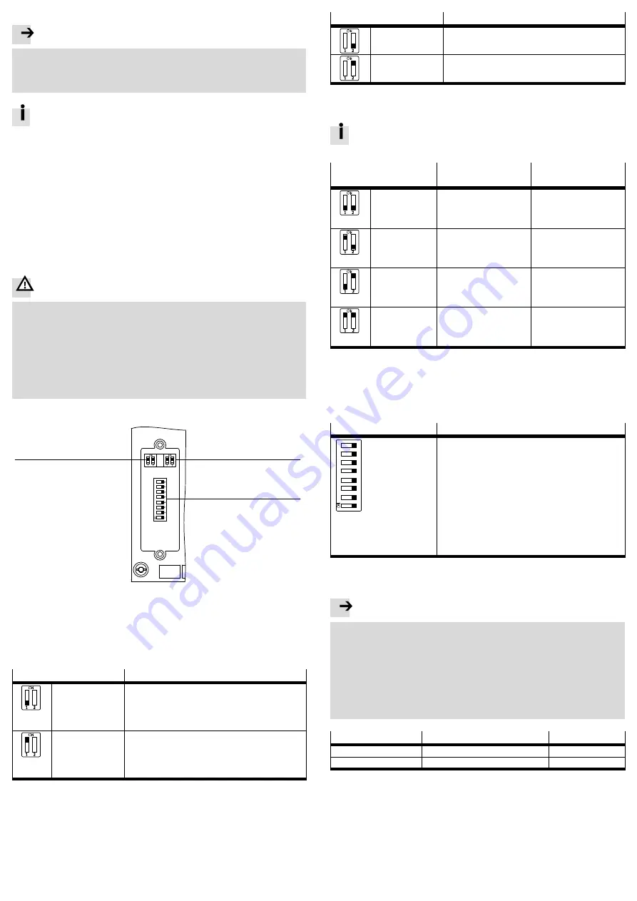
DIL switch elements
1
2
3
1
DIL switch 1:
– DIL 1.1: operating mode
– DIL 1.2: network protocol
2
DIL switch 2: diagnostic mode and
data field size
3
DIL switch 3: IP addressing
1)
Setting of the data field size is available only in the remote controller operating mode.
Fig. 5
6.1 DIL switch 1 – operating mode and network protocol
Setting DIL switch 1.1
Operating mode
DIL 1.1: OFF
(Factory setting)
Remote I/O
All functions of the CPX terminal are controlled directly by
the higher-order controller. A control block integrated into
the CPX terminal (e.g. CPX-CEC or CPX-FEC) works as a
passive function module without controller.
DIL 1.1: ON
Remote controller
A control block integrated into the CPX terminal
(e.g. B. CPX-CEC or CPX-FEC) takes over I/O control. This
operating mode is only useful if a control block is integ
rated into the CPX terminal.
Fig. 6
Setting DIL switch 1.2
Network protocol
DIL 1.2: OFF
(Factory setting)
EtherNet/I P
The CPX terminal uses the EtherNet/IP network protocol.
DIL 1.2: ON
Modbus TCP
The CPX terminal uses the Modbus TCP network protocol.
Fig. 7
6.2 DIL switch 2 – diagnostic mode or data field size
The function of DIL switch 2 is dependent on the set operating mode of the
CPX terminal (
è
Setting DIL switch 2
Diagnostics mode
(Remote I/O)
Data field size
(Remote controller)
DIL 2.1: OFF
DIL 2.2: OFF
(Factory setting)
I/O diagnostics interface and
status bits switched off
8 byte I/8 byte O for
communication of the bus
node with a control block
(e. B. CPX-FEC)
DIL 2.1: ON
DIL 2.2: OFF
I/O diagnostics interface is
switched on
32 byte I/32 byte O for
communication of the bus
node with a control block
(e. B. CPX-FEC)
DIL 2.1: OFF
DIL 2.2: ON
Status bits switched on
16 byte I/16 byte O for
communication of the bus
node with a control block
(e. B. CPX-FEC)
DIL 2.1: ON
DIL 2.2: ON
Reserved
64 byte I/64 byte O for
communication of the bus
node with a control block
(e. B. CPX-FEC)
1)
Setting of the diagnostic mode is available only in the remote I/O operating mode.
2)
Setting of the data field size is available only in the remote controller operating mode.
3)
Revision 12 and above
4)
Revision 13 and above
Fig. 8
6.3 DIL switch 3 – IP addressing
Setting DIL switch 3
IP addressing
12
34
56
7
8
3.8:
3.7:
3.6:
3.5:
3.4:
3.3:
3.2:
3.1:
2
7
=
2
6
=
2
5
=
2
4
=
2
3
=
2
2
=
2
1
=
2
0
=
128
64
32
16
8
4
2
1
The type of addressing or the host ID of the IP address of the
bus node is set via DIL switch elements 3.1 ... 3.8.
Possible settings:
0 = Dynamic addressing via DHCP/BOOTP
1 … 254 = Permissible address range
255 = Reset all IP parameters to factory setting
Factory setting: 0
Example:
2
1
+ 2
2
+ 2
5
= 2 + 4 + 32 = 38 (host ID)
Set IP address: 192.168.1.
038
Fig. 9
7
Ensuring the degree of protection
Note
Short circuit
Malfunction or damage to the electronics
Use connection technology with the required degree of protection e.g. plug
NECU-M-S-D12G4-C2-ET (
è
www.festo.com/catalogue).
Use cover caps to seal unused connections, e.g. cover cap ISK-M12
(
è
www.festo.com/catalogue).
Mount the DIL switch cover:
Check seal, place cover and push it down, tighten screws. Tightening torque
maximum 0.4 Nm.
Connection
Connecting hardware
Cover cap
Network connection (M12)
Plug NECU-M-S-D12G4-C2-ET
ISK-M12
Service interface (M12)
ISK-M12
1)
Connecting cable for operator unit (CPX-MMI)
Fig. 10
8
Parameterisation
The CPX terminal and the module described here can be parameterised with the
operator unit (CPX-MMI), the Festo Maintenance Tool (CPX-FMT) software or the
higher-level system.


