9
Note on module replacement
Caution
For CPX terminals with a continuously illuminated or flashing “Modify” LED (M),
parameterisation is not automatically created by the higher-level system when
the CPX terminal is replaced during servicing.
Before replacement, note required settings and make them again after re
placement.
When replacing a bus node with the setting [System start with saved para
meters], the CPX terminal is not parameterised automatically by the high
er-order controller.
The bus node CPX-FB36 is compatible with the bus node CPX-FB32:
A bus node CPX-FB32 can be replaced in existing applications by a bus
node CPX-FB36 (Revision 13 or higher) without changing the configuration
of the host system.
10
Start-up behaviour of the CPX terminal
If the “Modify” LED (M) lights up or flashes permanently after the system start,
“System start with saved parameterisation and saved CPX expansion” is set or
“Force” is active.
Additional information on parameterisation, module replacement and
start behaviour of the CPX terminal can be found in the module descrip
tion (
è
CPX-FB36-…).
11
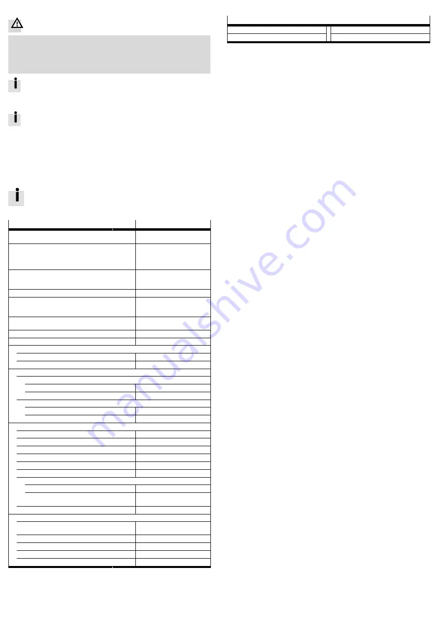
Technical data
Characteristic
Specification/value
General technical data
è
CPX system description
P.BE-CPX-SYS-…
Degree of protection through housing
in accordance with IEC 60529, completely
mounted, plug connector in plugged-in status or
equipped with cover caps.
IP65/IP67
Protection against electric shock
Protection against direct and indirect contact in
accordance with IEC 60204-1/EN 60204-1
Through the use of PELV circuits
(Protected Extra-Low Voltage)
Operating voltage supply U
EL/SEN
[V DC]
24 ± 25 %
Intrinsic current consumption at nominal
operating voltage 24 V from operating voltage
supply U
EL/SEN
[mA]
Typ. 100 (internal electronics)
Separation of network interface from operating
voltage supply U
EL/SEN
Galvanic
Load voltage supply U
VAL/OUT
[V DC]
24 ± 10 %
Mains buffering time
[ms]
10
Module code (CPX-specific)
Remote I/O
224
Remote controller
171
Module identifiers (CPX-MMI)
EtherNet/I P
Remote I/O
FB36 EtherNet/IP remote IO V2
Remote controller
FB36-RC EtherNet/IP Node
Modbus TCP
Remote I/O
FB36-MB Modbus TCP remote IO
Remote controller
FB36-MB-RC Modbus TCP node
Network-specific characteristics
Connection technology
2× socket, M12, D-coded, 4-pin
Protocol
EtherNet/I P or Modbus TCP
Transmission technology
Switched fast Ethernet
Specification
IEEE 802.3u (100Base-TX)
Transmission rate
[Mbit/s]
10/100 (full duplex/half duplex)
Minimum cycle time (RPI)
[ms]
1
Maximum data field size (input/output size)
Remote I/O
[byte]
64 I/64 O
Remote controller
[byte]
8 I/8 O, 16 I/16 O, 32 I/32 O or
64 I/64 O
Crossover detection
Auto-M DI/MDI-X
Cable specification
Cable type
Ethernet twisted pair cable,
screened
Transmission class
Category Cat 5/Cat 5e
Cable diameter
[mm]
6 … 8
Wire cross section
[mm
2
]
0.14 … 0.75; 22 AWG
Maximum cable length
[m]
100
1)
Connected products may only satisfy a lower degree of protection.
2)
Based on the Ethernet protocol IEEE 802.3
3)
Dependent on the setting of the DIL switch 2 and the revision of the bus node
4)
When using the plug NECU-M-S-D12G4-C2-ET from Festo
5)
Required for maximum connection length between network participants
Fig. 11
12
Specified standards
Version status
IEC 60204-1:2009-02
IEEE 802.3:2014-00
IEC 60529:2001-02
Fig. 12


