


USB interface [USB]
The USB interface (A-coded socket, USB specification 2.0) is used to save data and
results to external storage media.
– The data of the USB memory is stored in the /mnt/usb directory.
– The data is accessed through SysFile and CAA.File
è
CoDeSys libraries.
Requirements
– Maximum memory size: 32 GB
– Formatting: FAT32 (one partition only)
Note
Impermissible operating states of the controller result from high current
consumption at the USB interface.
Only storage media with a current consumption of
0.5A are used.
Note
Do not use storage media for continuous data recording.
The USB interface is only intended for user-monitored operation.
USB storage devices cannot be used to execute CoDeSys boot projects.
6
Transport and storage
Observe specifications on the environmental and storage conditions
è
12 Technical data.
7
Installation
7.1 Network
Note
Transmission errors due to faulty installation or excessive transmission rates.
Observe the line specifications in the documentation of the controller.
Note
Unauthorised access to the product can cause damage or malfunctions.
When connecting the product to a network:
Protect the network against unauthorised access. Measures for the protection
of the network, for example:
– Firewall
– Intrusion prevention system (IPS)
– Network segmentation
– Virtual LAN (VLAN)
– Virtual private network (VPN)
– Safety at physical access level (port security)
Additional information
è
directives and standards for security in information
technology, e.g.,IEC 62443, ISO/IEC 27001. An access password only protects
against unintentional modification.
7.2 Operating voltage supply U
EL/SEN
Note
Malfunction due to faulty installation.
Observe the information regarding the line specification, voltage supply and
earthing measures in the “Instructions for use of system CPX-E”
è
1.1 Further applicable documents.
1. Ensure the voltage supply is deactivated.
2. Connect the lines to the terminal strip according to the “Instructions for use of
system CPX-E”
è
1.1 Further applicable documents.
8
Commissioning
Information regarding the commissioning of system CPX-E can be found in
the “Instructions for use of system CPX-E.” Information on the parameters
can be found in the “Description of system CPX-E” and in the descriptions
of the modules used
è
1.1 Further applicable documents.
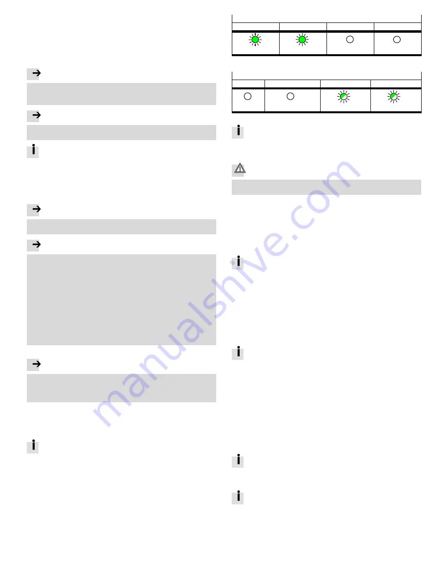
8.1 Behaviour of the display components after error-free commissioning
Module-specific LED indicators
[PS] (green)
[PL] (green)
[SF] (red)
[M] (yellow)
Lights up
Lights up
Off
Off
Fig. 13
Network-specific LED indicators for PROFINET IO
[NF] (red)
[M/P] (green/yellow)
[XF1] (green)
[XF2] (green)
Off
Off
Lights up or flashes
Lights up or flashes
Fig. 14
Information on error elimination in case of deviating behaviour can be
found in the “Description of system CPX-E” and in the descriptions of the
modules used
è
1.1 Further applicable documents.
8.2 Commissioning with CoDeSys
Caution
Risk of injury due to uncontrolled movements of the connected actuators.
Perform test runs of projects and applications without active actuators first.
For the configuration, parameterisation and programming of the product:
useCoDeSys V3.
Prerequisites
– PC (Windows 7 or higher) with Ethernet interface
– Components for network connection
– Programming software CoDeSys V3
– Package CPX-E-CEC compliant with firmware of product
è
www.festo.com/sp
Preparations
For the installation and operation of programming software CoDeSys V3,
administration rights are required.
1. Install CoDeSys V3.
2. Start CoDeSys V3 with administration rights.
3. Open Package Manager
è
Menu command [Tools] [Package Manager].
4. Install the current Package for CPX-E-CEC
è
online help of CoDeSys
V3
è
“PackageManager”.
5. Restart CoDeSys V3 in order to use the new Package.
6. Connect the controller to the network connection [ETH1] or [ETH2] through
aswitch/hub or directly to the PC
è
7.1 Network.
7. Adapt the network settings
è
Menu command [Online] [Scan Festo Devices]
è
online help of CoDeSys V3
è
“Scan Festo Devices”.
The current version of package CPX-E-CEC for CoDeSys V3 can be found on
the Support Portal of Festo
è
www.festo.com/sp.
Additional support can be found in the product-specific help
è
Online
help of CoDeSys V3
è
“Erste Schritte”.
8.3 Commissioning on higher-order controller
A device description file is available for the commissioning of CPX-E-CEC-... on
aPROFINET master system.
9
Diagnostics and fault clearance
9.1 Diagnostics options
For the diagnostics of errors, various possibilities are available:
– Internal system diagnosis
– LED indicators on the product
9.2 Internal system diagnosis
The internal system diagnostics is described in the “Description of system
CPX-E” and in the descriptions of the modules used
è
1.1 Further applicable documents.
9.3 LED displays
This document describes the module- and network-specific LED indicators.
The system-specific LED indicators are described in the documentation for
system CPX-E
è
1.1 Further applicable documents.


