8.1 Hardware and memory
CECC-...
D
LK
S
Processor (CPU)
400 MHz
Processing time
Approx. 250 μs/1k instructions
RAM memory (projects, variables, constants)
16 MB, from Revision 04:
44 MB
44 MB
Flash memory (boot project, project archive,
web visualisation, application data)
2 MB, from Revision 04:
16 MB
16 MB
Flag (flag memory)
8 KB
Inputs
8 KB
Outputs
8 KB
Remanent variables
7120 bytes
Fig. 19 Hardware and memory
8.2 Remanent variables
The controller makes available a maximum of 7120 bytes for storing remanent
variables (retain and persistent-retain variables). They are automatically shared
based on the variable declaration within the application.
The following sample combinations for assigning the memory are possible.
Retain variable
Persistent-retain variable
7120 bytes
0 bytes (only if there is no persistent variable list)
0 bytes
7076 bytes (44 bytes for identification)
300 bytes
7076
-
300 bytes = 6776 bytes (44 bytes for identification)
x byte
7076
-
x bytes (44 bytes for identification)
Fig. 20 Memory assignment of the remanent variables (examples)
Note
Error
due to memory overflow.
Comply with maximum memory capacity for remanent variables: 7120 bytes.
9
Specified standards
Version
IEC 60204-1: 2005, modified
EN60204-1:2006
IEC 60950-1:2005, mo Cor.:2006 +
A1:2009, mo A1:2009/Cor.:2012 +
A2:2013, modified
EN 60950-1:2006 + A11:2009 + A1:2010 +
A12:2011 + AC:2011 + A2:2013
IEC 61010-1 Edition 3
EN61010-1:2010
IEC 61131-3:2013 Edition 3.0
EN61131-2:2007
IEC 62368-1:2014, mo Cor.:2015
EN62368-1:2014 + AC:2015
UL60950-1 Edition 2
CAN/CSA-C22.2 No.60950-1-07 Edition2
UL61010-1 Edition3, May 11, 2012,
RevisedApril 29,2016
CAN/CSA-C22.2 No.61010-1-12 Edition3,
Update No.2 April 2016
UL61010-2-201 Edition1 -
Revisiondate2017/02/20
CAN/CSA C22.2 No.61010-2-201:14 Edition1,
Issue Date 2014/01/01
UL62368-1 Edition 2
CAN/CSA-C22.2 No.62368-1-14 Edition2
Fig. 21 Standards specified in the document
10
Appendix
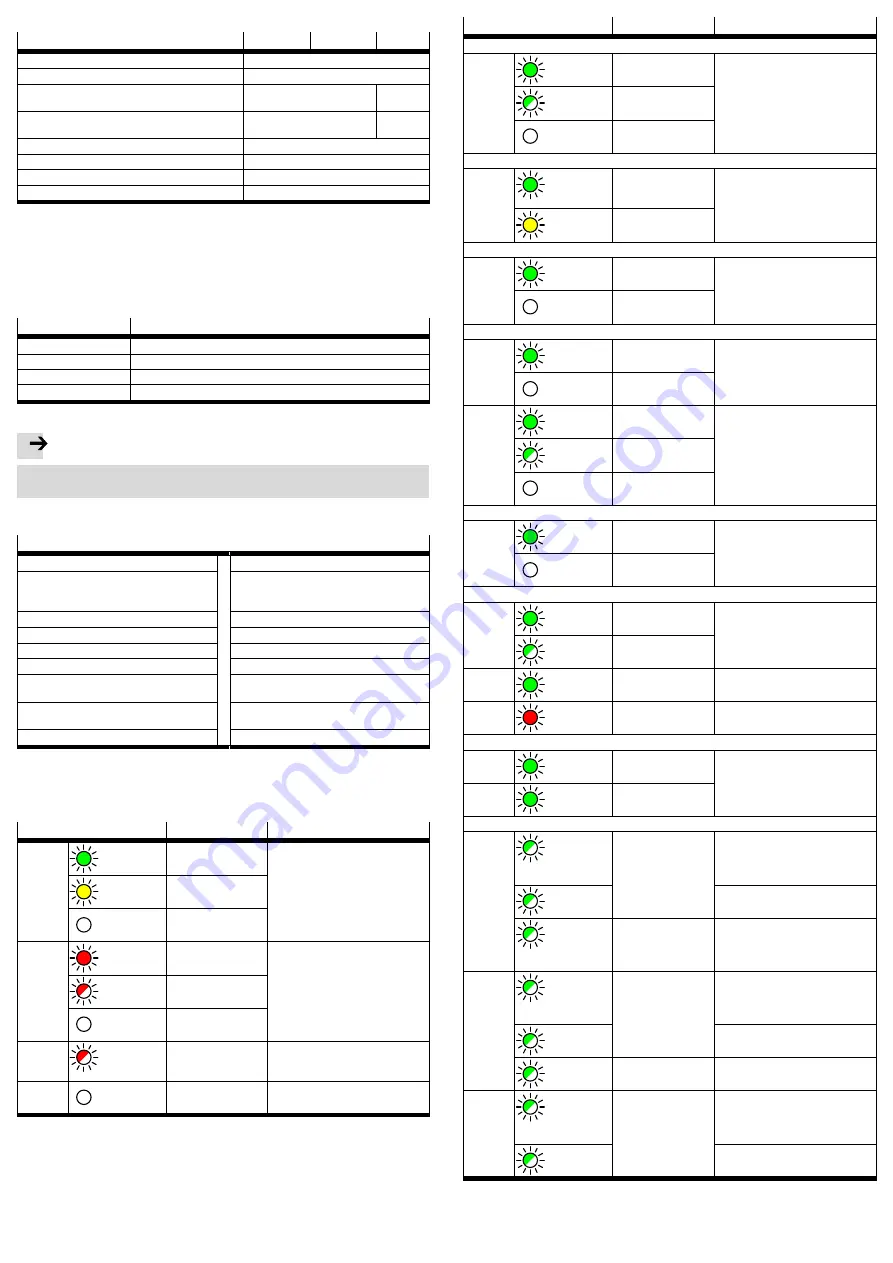
10.1 All LED indicators
LED
Meaning
Explanation
Run
Lights up
green
Program running
Application status
Lights up
yellow
Program is stopped
Off
Run-time system is
not running
Error
Lights up
red
Class 4 error
PLC run-time error
Flashes
red
Class 2 error
Off
No error/class 1 error
Net
Flashes
red
Controller has been
identified in
the network
Identification, e.g. through Festo
Field Device Tool (FFT)
Mod
Off
–
Reserved
LED
Meaning
Explanation
Operating voltage supply X1 (V-El.)
24
Lights up
green
Controller is ready
for operation
Power supply
Flashes
green
Undervoltage
Off
Controller is
switched off
I/O interfaces X2
…
X4 (digital input, digital output)
.0
…
.7
Lights up
green
At the input, 24 V is
present, e.g. at X2.1
or X3.5
Voltage is present at the inputs or
outputs
Lights up
yellow
At the output, 24 V is
present, e.g. at X4.0
Infeed of load voltage supply for I/O interfaces X5
24
Lights up
green
Voltage is present
Power supply for the I/O interfaces
Off
No voltage
Ethernet X8
Left
Lights up
green
Data transfer with
100 Mbit/s
Speed LED: speed of data transfer
Off
Data transfer with
10 Mbit/s
To
the right
Lights up
green
Connection is made
Link/activity LED: connection and
data transfer
Flashes
green
Data transfer is active
Off
No connection
Infeed of load voltage supply for encoder X11 (24 V DC/UE)
UE
Lights up
green
Voltage is present
Power supply for encoder
Off
No voltage
IO-Link interfaces CECC-LK: X12…X16 (IOLM…, OLD), CECC-S: X15…X16 (IOLM, OLD)
L+
Lights up
green
IO-Link Master is act
ive
Status indication
Flashes
green
IO-Link Master is not
ready for operation
C/Q
Lights up
green
Connection is made
Link/activity LED:
connection and data transfer
C/Q
Lights up
red
Data transfer is
inactive
Link/activity LED:
connection and data transfer
Serial interface modules CECC-S: X12 and X13 (RS232-1/-2)
TX
Lights up
green
CECC transmits data
Data transmission
RX
Lights up
green
CECC receives data
Multiple interface CECC-S: X14 (ENC/RS485/RS422)
A+
Flashes
green
Encoder ticks track A
Encoder turns slowly, LED flashes in
the cycle of the rotary frequency and
visualises the counting pulses
(encoder ticks)
Flickers
green
Encoder rotates quickly
Flickers
green
Transmitted data for
RS422
Transmitted/received
data with RS485
Display of data transmission
B+
Flashes
green
Encoder ticks track B
Encoder turns slowly, LED flashes in
the cycle of the rotary frequency and
visualises the counting pulses
(encoder ticks)
Flickers
green
Encoder rotates quickly
Flickers
green
Received data with
RS422
Display of data transmission
N+
Flashes
green
Encoder ticks zero
track
Encoder turns slowly, LED flashes in
the cycle of the rotary frequency and
visualises the counting pulses
(encoder ticks)
Flickers
green
Encoder rotates quickly
Fig. 22 LED indicators


