background image


FES BATTERY PACK GEN2 14S, Version 1.23                                         September 2019


Page 13 of 26 

 
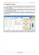
3.3 FES BMS Control software 
 

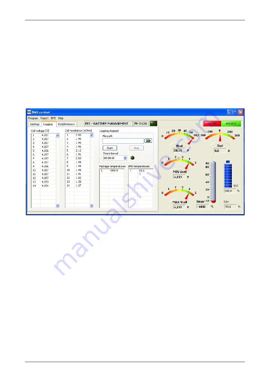
If you want to monitor and log how voltage levels of each cell in the battery pack are 

rising  during  charging,  you  can  use  dedicated  FES  BMS  Control  software  on  PC  (or  via 
optional FES LCD display).  

In case that some problems are discovered during charging, log file can be created 

and  later  you  can  send  it  by  email  to  FES  manufacturer.  It  can  help  us  to  discover  the 
problem and find a suitable solution. 

How  to  install  and  use  FES  BMS  Control  software  is  described  step  by  step  in 

dedicated FES BMS Control manual, which can be obtained from FES dedicated website, in 
download section.


Cells voltage levels, and calculated internal resistance values on fully charged battery pack 


Содержание GEN2 14S

Страница 1: ... PACK GEN2 14S manual With integrated BMS Battery Management System Version 1 22 Type FES GEN2 14S LZ design d o o Brod 3D 1370 Logatec Slovenia tel 386 59 948 898 info lzdesign si www front electric sustainer com ...

Страница 2: ...pack Chargers 8 3 1 Available chargers 8 3 2 Standard charger to Battery pack connection and charging 10 3 3 BMS Control software 13 4 Before flight 14 4 1 Installing the batteries 15 4 2 Preflight test run 16 5 After landing 18 5 1 Removing the batteries 18 6 Maintenance 19 6 1 BMS firmware upgrade 20 7 Transport 21 7 1 Car transport 21 7 2 In glider trailer 23 7 3 Ship train transport 23 8 Stora...

Страница 3: ...nusual 1 1 Limited Warranty This product is warranted to be free from defects in materials or workmanship for one year from the date of purchase Within this period LZ design will at its sole option repair or replace any components that fail in normal use Such repairs or replacement will be made at no charge to the customer for parts and labour The customer shall be responsible for any transportati...

Страница 4: ... 3mm contact for pole 2 1 Technical data Battery pack type FES GEN2 14S Weight of single battery pack 15 7 kg Box dimensions WxLxH without terminals and ventilators 154 x 220 x 257mm Cells producer Kokam South Korea Electrochemical system NMC LiMnNiCoO2 Cells type SLPB100216216H Average capacity of each cell 41 Ah Number of cells 14 Energy storage capacity 2 1 kWh Maximum total voltage 58 3 V Mini...

Страница 5: ...FES BATTERY PACK GEN2 14S Version 1 23 September 2019 Page 5 of 26 2 2 Drawing ...

Страница 6: ...al layout of the pack Top view of FES GEN 2 battery pack Plus pole RADSOK terminal fi 10 3mm Minus pole RADSOK terminal fi 8 0mm DATA cable connector with spring locks BMS ON OFF switch Balancing LEDs 1 14 BMS POWER LED ERROR LED Strap for carrying BMS cooling plate ventilators ...

Страница 7: ...milled from Aluminum and black anodized To improve dissipation of the heat there are two small ventilators on top of the upper plate which starts running when upper plate reach preset temperature 50 C Balancing of each cell is indicated by green light emitting diode LED Note BMS starts balancing cells only during charging and above pre set balancing start voltage 4 10V BMS DATA AND INITIAL SETTING...

Страница 8: ...equired input voltage 230V 50 60 Hz Note Each charger is preset with suitable settings for FES GEN2 14S and works only if it communicates with BMS circuit board inside of the battery pack 3 1 Available chargers 1 FES KOP602 standard equipment FES system comes with two chargers FES KOP602 maximum charging current 9A required input voltage is 230V 50 60 Hz KOP 602 BMS Charger 2 FES KOP1001 optional ...

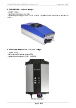
Страница 9: ...al charger 2300W 5 6 kg maximum charging current 45A required input voltage is 80V 265V 47 63 Hz suitable for US customers as it works on 110V 4 FES R2300 BMS version optional charger 2000W 6 1 kg with maximum charging current 35A required input voltage is 230V 50 60 Hz FES R2300 charger ...

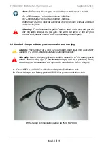
Страница 10: ... set first marked as A second marked as B must be always used in pair 3 2 Standard charger to Battery pack connection and charging Caution Place charger on a safe secure position Keep away from dust direct sunlight fire smoke childrens and any unatendent person Warning Before charging physical condition inspection of the battery packs should be done Any sign of mechanical damage such as a puncture...

Страница 11: ...fter some time cooling fans in charger starts 6 In normal mode green BMS Power LED of BMS is starting flashing This means that the BMS is turned ON but not necessary balancing Balancing starts when one cell reaches pre set value usually 4 1V could be changed by BMS Control Software If any of 14 green LED cell balancing indicators is ON it means that this cell has slightly higher voltage compared t...

Страница 12: ...age Using two packs with too much difference in voltage levels is not allowed Maximum 1V difference between total voltages of both packs is acceptable For instance Pack 1 58 1V average 4 150 per cell Pack 2 57 1V 4 080V per cell this is just acceptable Bigger voltage difference is not acceptable Caution When thunderstorm is approaching stop charging immediately and disconnect the charger from the ...

Страница 13: ... display In case that some problems are discovered during charging log file can be created and later you can send it by email to FES manufacturer It can help us to discover the problem and find a suitable solution How to install and use FES BMS Control software is described step by step in dedicated FES BMS Control manual which can be obtained from FES dedicated website in download section Cells v...

Страница 14: ...er load is bigger short runways high altitude runways hot summer conditions Valid for FES Self sustainers Before each flying day battery packs should be recharged especially if motor was significantly used during previous flights and long cross country flight is planned so that maximum energy will be available when needed Note It is recommended to recharge Battery packs just a day or two before fl...

Страница 15: ... fixation plates in the middle of rear pack above carrying strap and tighten fixation knob 8 Secure forward battery in the same way 9 Lift power cables from side support 10 Plug in shorter cable with 8mm pin in BLUE or BLACK housing to minus marked 8mm socket of front battery pack 11 Plug in longer cable with 10mm pin in RED housing to plus marked 10mm socket of rear battery pack 12 Insert DATA ca...

Страница 16: ...rminal 6 Close battery compartment cover and seal it with tape 7 Seat into the cockpit of the glider and close canopy 8 Check that nobody is in line of propeller disk or in front of sailplane 9 Switch ON the FCU and wait a few seconds until appearance of normal screen 10 Switch ON the Power switch 11 Wait about 5 seconds so that charge level indicated as bottles reaches 100 value this happens only...

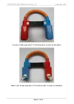
Страница 17: ...TTERY PACK GEN2 14S Version 1 23 September 2019 Page 17 of 26 Top view of right angle type of Connecting cable as used on LAK gliders Bottom view of right angle type of Connecting cable as used on LAK gliders ...

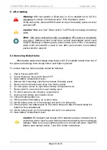
Страница 18: ...procedure should be followed 1 Check Power switch OFF 2 Check Sailplane main switch fuse OFF 3 Open battery compartment cover 4 Remove the Connecting cable from terminals of battery packs 5 Remove red and black power plugs from battery packs 6 Fix both power cables on right side of battery compartment wall 7 Remove DATA connectors from each battery pack 8 Fix DATA cable to side of battery compartm...

Страница 19: ...harging and number of charging cycles With poor treatment of the battery packs their cells internal resistance will be rising faster and so calculated SOH level will become lower When it will be as low as 50 it would be time to think about replacement of the battery packs at least the cells BMS electronic could be reused Poor condition of the cells can be recognizable also during powered flight mu...

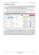
Страница 20: ... it is required suitable bin file which we can send to the customer by email Please save it to the chosen location on PC disk drive Connect BMS Charger PC cable to BMS and to USB port of PC Run BMS Control Software cancel any initial error messages which might appear note that for firmware upgrade green PRESENT indication is not required From upper menu choose BMS then Firmware upgrade and browse ...

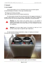
Страница 21: ...ransportation box should be additionaly secured so that it can not move backward during acceleration or forward at braking Warning For safety reasons and common sense it is not allowed to transport battery packs in the car cockpit for instance behind drivers or co drivers seat or infront of the co driver seat as in case of accident it could be very dangerous Warning Do not leave battery packs in t...

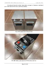
Страница 22: ...2019 Page 22 of 26 For advanced protection during transportation storage or charging we developed pair of FES Stainless steel boxes optionaly available Pair of FES stainless steel storage boxes FES GEN2 Battery pack placed into FES Stainless steel box ...

Страница 23: ...oved 7 3 Ship train transport When your glider is transported by RORO ship or train in its trailer in Container ship with or without its trailer we suggest placing FES battery packs into battery compartment of the glider so they are properly fixed as during flight Another possibility is to place battery packs into FES Stainless steel boxes and fix them to the corner of the container It is recommen...

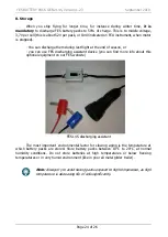
Страница 24: ...r you can use FES discharging assistant device you can find more info about this optional equipment on our FES website FES 14S discharging assistant The most important environmental factor for slowing aging is the temperature at which battery packs are stored Store battery packs between 10 C to 20 C at normal humidity conditions Do not store batteries at high temperatures or below freezing tempera...

Страница 25: ...S BATTERY PACK GEN2 14S Version 1 23 September 2019 Page 25 of 26 Note Warning sticker as above with some basic information regarding storage is located on rear vertical wall of each FES GEN2 battery pack ...

Страница 26: ...arch 2015 Update with drawing transportation box and sticker Version 1 14 July 2015 Minor updates Version 1 15 October 2016 New maintenance section Version 1 16 November 2016 Additional info about DATA connector Version 1 17 September 2017 Minor correction about BMS switching OFF and new info about powerfull R2300 charger Version 1 18 October 2017 Updated Storage and transport new assembly drawing...

Отзывы: